Parcel alarm that keeps going
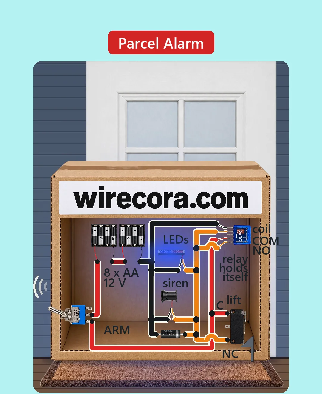
Lift the parcel and a siren sounds with red and blue strobe flashes. Put it back down and it keeps going, because one relay holds itself on. It stops only when the owner flips the ARM switch off.
- 8 parts
- 5 wiring steps
- No code needed
- 12 V supply
Quick answer
The short version. Every pin is in the full wiring below.What you need
- 12 V battery pack: two 4 x AA holders in series
- 12 V SPDT relay, SRD-12VDC type
- Lever microswitch, normally closed contact used
- MTS-102 mini toggle switch as the ARM switch
- 1N4007 diode across the relay coil
- 12 V piezo siren
- 12 V red and blue LED strobe with its own flasher
- A box for the parcel, a mat and wire
How to wire it
- Battery plus (first holder) to the ARM toggle's common lug.
- ARM toggle's ON lug to relay COM and to the microswitch's C terminal.
- Microswitch NC terminal to relay NO, to the relay's coil plus side (CA), to the 1N4007 band, and to the red leads of the siren and the strobe.
- Relay coil minus side (CB), 1N4007 anode, black leads of the siren and the strobe, and the battery minus (second holder) all to one ground line.
- Leave the toggle's other outer lug, the microswitch NO terminal and the relay NC pin unconnected.
Before you power it: 12 V DC from AA cells, drawing about 0.36 A while it sounds. It only makes light and noise, but a 105 dB siren is loud, so test it away from your ears. Switch ARM off before you pick up your own parcel, and arm it only once the box is down.
Parts list
- 12 V battery pack: two 4 x AA holders in series (eight AA cells)
- 12 V SPDT relay, SRD-12VDC type (coil about 400 ohm, 30 mA; contact rated 10 A at 30 V DC)
- Lever microswitch, normally closed contact used (C and NC; Omron SS-5GL type)
- MTS-102 mini toggle switch as the ARM switch, in the battery lead
- 1N4007 diode across the relay coil
- 12 V piezo siren (about 210 mA, about 105 dB)
- 12 V red and blue LED strobe with its own flasher (about 120 mA, assumed from listings)
- A box for the parcel, a mat and wire
Wiring, step by step
- Battery plus (first holder) to the ARM toggle's common lug. The two holders are joined minus of the first to plus of the second.
- ARM toggle's ON lug to relay COM and to the microswitch's C terminal. This line is the live bus.
- Microswitch NC terminal to relay NO, to the relay's coil plus side (CA), to the 1N4007 band, and to the red leads of the siren and the strobe. This is the alarm line.
- Relay coil minus side (CB), 1N4007 anode, black leads of the siren and the strobe, and the battery minus (second holder) all to one ground line.
- Leave the toggle's other outer lug, the microswitch NO terminal and the relay NC pin unconnected.
How it works
- While the parcel sits on the mat, the microswitch lever is pressed and its NC contact is open. Nothing is powered: 0 mA while it waits.
- Lift the parcel and the lever lets go. NC closes and 12 V reaches the relay coil, the siren and the strobe together.
- About 10 ms later the relay pulls in and its own NO contact also joins the bus to the alarm line. Setting the parcel down opens the microswitch again, but the relay now feeds the alarm itself, so it holds on.
- Flipping ARM off cuts the battery lead. The relay lets go and the siren and strobe stop. Flip it on again with the parcel down and it is armed and quiet.
- The 1N4007 across the coil, band on the plus side, takes the voltage spike when the coil switches off.
What the video simplifies
- The front of the box is cut away and the ARM switch is drawn on the outside so you can see everything. In a real build it hides under a flap or is a key switch.
- The lift switch is worked in the picture by a steel feeler rod through a slot in the floor: the mat pushes the rod up and its wedge holds the lever in. A real build would use a mat or roller actuator; the wedge is a stand-in.
- The relay and switches are drawn larger than real so their pins can be read; the battery holders, siren and strobe are drawn smaller. Nothing is to one scale.
- The siren and strobe currents are typical values from product listings, not measurements. The strobe's flash pattern is its own flasher's. The siren sound is softened, and the bounce and the sound arcs are drawn for effect.
- Below about 9 V the relay may not latch any more, so change the cells in time.
- This circuit was checked by datasheets and calculation, not built.
You found this by searching. Here's the whole path.
- Read how it works
- See it work
- Build it
- Show it
Thirty seconds of video shows the circuit doing its job.
12 V DC from AA cells, drawing about 0.36 A while it sounds. It only makes light and noise, but a 105 dB siren is loud, so test it away from your ears. Switch ARM off before you pick up your own parcel, and arm it only once the box is down.
Built it, or stuck halfway? Post a photo in the Wirecora Discord. Questions get an answer every day.
What to build next
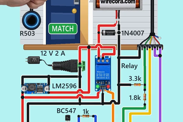 Same relay + buzzerFingerprint door lock with an Arduino and an R503Touch the sensor's ring with an enrolled finger: about half a second later the ring turns blue, the relay clicks and the solenoid pulls its bolt back, so the little door swings open with a push.
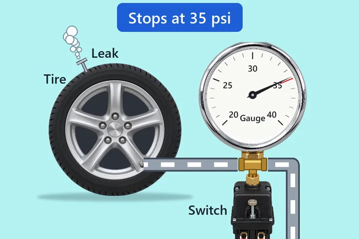 Next step: adds a pumpTyre pump that stops itself at 35 psiA pressure switch on the tyre valve tells the pump when to stop and when to start again.
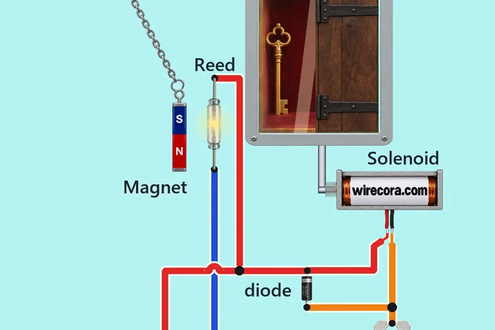 Something new: a reed switchMagnet-key hatchA magnet on a chain swings up beside a glass reed switch.