Magnet-key hatch
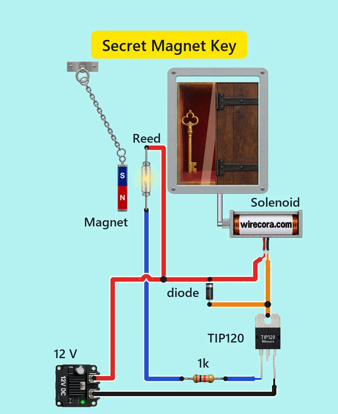
A magnet on a chain swings up beside a glass reed switch. The switch closes, the solenoid pulls and a small oak door slides aside to show a key. When the magnet swings away a spring shuts the door again.
- 8 parts
- 5 wiring steps
- No code needed
- 12 V supply
Quick answer
The short version. Every pin is in the full wiring below.What you need
- 12 V 2 A DC power supply
- Glass reed switch, normally open
- 1k resistor
- TIP120 transistor
- 1N4007 diode across the solenoid coil
- 12 V lock-style solenoid
- Small 10 x 5 x 3 mm N42 neodymium magnet on a chain
- A light sliding door
How to wire it
- Supply plus to one lead of the reed switch, to the band (cathode) of the 1N4007 and to the red lead of the solenoid.
- The other lead of the reed switch to one end of the 1k resistor, and the other end of the 1k resistor to the TIP120 base (pin 1).
- Black lead of the solenoid to the TIP120 collector.
- 1N4007 anode to the same point as the solenoid's black lead and the collector.
- Supply minus to the TIP120 emitter (pin 3).
Before you power it: 12 V DC. The solenoid coil gets very hot if it stays on, so never leave a magnet sitting by the reed.
Parts list
- 12 V 2 A DC power supply
- Glass reed switch, normally open (switches up to 200 V, 0.5 A, 10 W; no plus or minus side)
- 1k resistor, 1/4 W, between the reed switch and the TIP120 base
- TIP120 transistor (a Darlington power transistor, 60 V, hFE at least 1000)
- 1N4007 diode across the solenoid coil
- 12 V lock-style solenoid (coil about 18.5 ohm, about 650 mA, rated for 1 to 10 s at a time)
- Small 10 x 5 x 3 mm N42 neodymium magnet on a chain
- A light sliding door, a return spring and a rod from the solenoid to the door
Wiring, step by step
- Supply plus to one lead of the reed switch, to the band (cathode) of the 1N4007 and to the red lead of the solenoid. These three meet on the plus line.
- The other lead of the reed switch to one end of the 1k resistor, and the other end of the 1k resistor to the TIP120 base (pin 1).
- Black lead of the solenoid to the TIP120 collector. Use the metal tab (pin 4), which is the same collector as pin 2, and trim the middle lead short.
- 1N4007 anode to the same point as the solenoid's black lead and the collector. The band end stays on the plus line, so the diode sits across the coil.
- Supply minus to the TIP120 emitter (pin 3).
How it works
- With no magnet near, the reed switch is open, the TIP120's base gets no current and the solenoid is off.
- When the magnet comes up beside the glass with its long side parallel to it, the reed switch closes. About 10 mA flows through the 1k resistor into the TIP120 base.
- The TIP120 switches on and about 0.6 A flows through the 12 V solenoid. The slug pulls a steel rod and the light door slides open.
- When the magnet swings away the reed switch opens, the TIP120 turns off and a spring shuts the door. The 1N4007 soaks up the spike from the coil at turn-off.
What the video simplifies
- The swing is slowed. A real fast swing only makes the door twitch, since it stays open only while the magnet is by the reed.
- The magnet is drawn as a large bar hanging straight. A real 10 x 5 x 3 mm magnet is much smaller, and the chain sways and tilts.
- The door and the rod's travel are drawn much larger than life. A real slug moves about 10 mm, so the door must be very light, and a wider opening needs a lever. The hinges on the door are decoration and so is the glint on the key; there is no lamp.
- The parts are not drawn to one scale. The distance at which the reed closes is calculated, not measured: for the small magnet, closest approach about 11 to 14 mm from the glass axis. Mount the reed at the end of the swing, with the magnet at rest at least 3 cm from the glass, or it will hold the coil on. A bigger magnet needs more distance.
- This solenoid is made for 1 to 10 s at a time. If a magnet stays by the reed the coil stays on and can burn, so use a timer in a real build. Any strong magnet opens it: a fun trick, not security.
- This circuit was checked by datasheets, calculation and ngspice simulation, not built.
You found this by searching. Here's the whole path.
- Read how it works
- See it work
- Build it
- Show it
Next: see it work
Thirty seconds of video shows the circuit doing its job.
Then build it
12 V DC. The solenoid coil gets very hot if it stays on, so never leave a magnet sitting by the reed.
Then show it
Built it, or stuck halfway? Post a photo in the Wirecora Discord. Questions get an answer every day.
What to build next
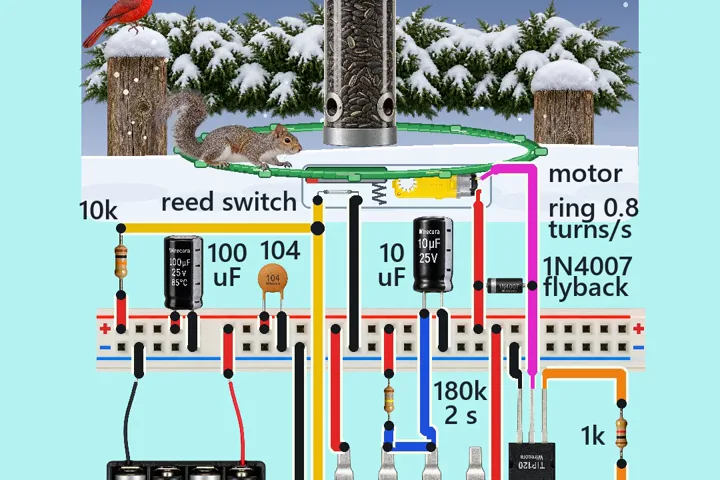 Same reed switch + TIP120Spinning bird feeder perch that turns when a squirrel climbs onA squirrel hops onto the feeder's perch ring and the ring starts to turn.
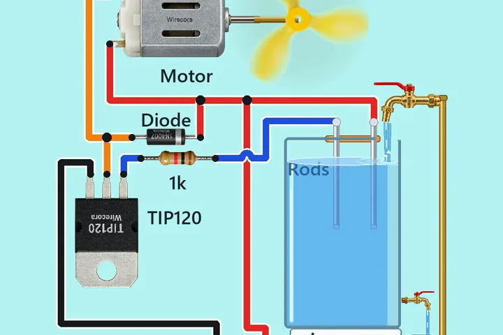 Next step: adds a motorWater-touch motor switchTwo steel rods stand in a tank.
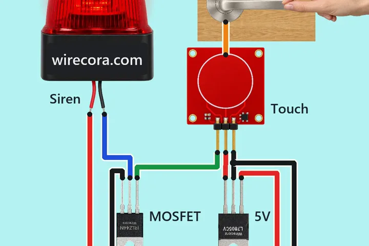 Something new: an MOSFETDoor handle touch alarmWhile a hand holds the metal door handle, a red strobe siren flashes and wails.