Spinning bird feeder perch that turns when a squirrel climbs on
A squirrel hops onto the feeder's perch ring and the ring starts to turn. The squirrel lets go and hops onto a post, and about two seconds after it climbed on, the ring stops. A small cardinal can eat on the same ring and nothing moves, because it is too light to start it. No code and no microcontroller.
- 13 parts
- 12 wiring steps
- No code needed
- 6 V supply
Quick answer
The short version. Every pin is in the full wiring below.What you need
- NE555 timer, DIP-8
- TIP120 Darlington transistor, TO-220
- 1N4007 diode across the motor
- Reed switch, normally open
- Small bar magnet
- Soft spring under the perch ring
- TT gear motor, 1:48
- 4 x AA holder, 6 V
- Resistors 180k, 10k and 1k, 1/4 W each
- 10 uF 25 V electrolytic capacitor
- 100 uF 25 V electrolytic capacitor
- 100 nF ceramic capacitor, marked 104
- A bird feeder with a turning perch ring
How to wire it
- Battery plus (red) to the + rail and battery minus (black) to the - rail.
- 555 pin 8 (VCC) and pin 4 (RESET) to +.
- 555 pin 1 (GND) to -.
- Reed switch: one end to - and the other end to 555 pin 2 (TRIG).
- 10k resistor from pin 2 to +.
- 180k resistor from + to pin 7 (DISCH), and a short wire joining pins 7 and 6 (THRES).
- 10 uF capacitor from pin 6 to the - rail: plus lead to pin 6, stripe (minus) to -.
- 555 pin 3 (OUT) through the 1k resistor to the TIP120 base (B).
- TIP120 emitter (E) to the - rail.
- TIP120 collector (C) to one motor wire, and the other motor wire to the + rail.
- 1N4007 across the motor: band (cathode) on the motor wire that goes to +, plain end on the wire that goes to the TIP120 collector.
- 100 uF capacitor and 100 nF (104) capacitor across the + and - rails: plus lead of the 100 uF to +, stripe to -.
Before you power it: Everything runs on 6 V from four AA cells; keep the electronics in a closed, rain-proof box and take the cells out when you store it. The motor draws about 0.5 A, and up to about 1.3 A if the ring jams (the TIP120 then turns about 1.2 W into heat, under its 2 W limit with no heatsink), so keep fingers and fur out of the ring.
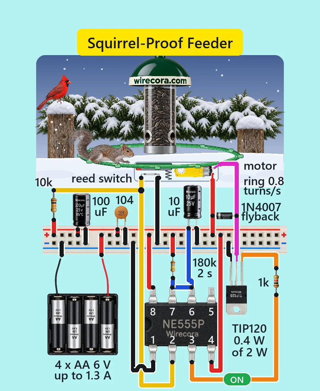
Parts list
- NE555 timer, DIP-8 (4.5 to 16 V; pin 5 is left open)
- TIP120 Darlington transistor, TO-220 (B, C, E from the left with the print facing you; the metal tab is the collector)
- 1N4007 diode across the motor (the flyback diode; the band is the cathode)
- Reed switch, normally open (0.5 A; closes when a magnet lies along it)
- Small bar magnet, on the feeder's non-turning collar, lying along the reed switch
- Soft spring under the perch ring (it sinks its full 8 mm under about 200 g; a design choice)
- TT gear motor, 1:48 (3 to 6 V; 200 rpm at 6 V with no load; not polarised) turning the ring through a small gear
- 4 x AA holder, 6 V (6.4 V with fresh alkaline cells)
- Resistors 180k, 10k and 1k, 1/4 W each
- 10 uF 25 V electrolytic capacitor (sets the time; the stripe side is minus)
- 100 uF 25 V electrolytic capacitor (across the supply, steadies it against motor noise; the stripe side is minus)
- 100 nF ceramic capacitor, marked 104 (across the supply)
- A bird feeder with a turning perch ring (the Short draws one about 25 cm across), and a small box to keep the electronics dry
Wiring, step by step
- Battery plus (red) to the + rail and battery minus (black) to the - rail. Put a power switch in the red lead.
- 555 pin 8 (VCC) and pin 4 (RESET) to +.
- 555 pin 1 (GND) to -. Pin 5 (CONT) is left unconnected; a 10 nF to - is an optional guard.
- Reed switch: one end to - and the other end to 555 pin 2 (TRIG).
- 10k resistor from pin 2 to +. It holds pin 2 high while the reed is open.
- 180k resistor from + to pin 7 (DISCH), and a short wire joining pins 7 and 6 (THRES).
- 10 uF capacitor from pin 6 to the - rail: plus lead to pin 6, stripe (minus) to -.
- 555 pin 3 (OUT) through the 1k resistor to the TIP120 base (B).
- TIP120 emitter (E) to the - rail.
- TIP120 collector (C) to one motor wire, and the other motor wire to the + rail.
- 1N4007 across the motor: band (cathode) on the motor wire that goes to +, plain end on the wire that goes to the TIP120 collector.
- 100 uF capacitor and 100 nF (104) capacitor across the + and - rails: plus lead of the 100 uF to +, stripe to -.
How it works
- While nobody is on the perch the reed switch is open, so the 10k holds pin 2 near the supply voltage (6 V). The 555 output is LOW, the TIP120 is off and the motor is still.
- A cardinal (45 g) presses the spring only about 1.8 mm of its 8 mm travel. The magnet stays too far from the reed switch, so nothing starts.
- A squirrel pushes the ring down, the magnet comes within about 7 mm of the reed switch and it closes. That pulls pin 2 to ground, below one third of the supply (2 V), and the 555 starts its timing run.
- Pin 3 goes HIGH and pushes about 3 mA through the 1k into the TIP120 base. The TIP120 switches the motor's minus side and the motor turns the ring at about 0.8 turns a second.
- The run lasts 1.1 x 180k x 10 uF = 1.98 s (about 1.6 to 2.4 s with a capacitor tolerance of 20 percent). If the squirrel has not let go and the reed is still closed when the time ends, the output stays HIGH until it does, then stops. When the 555 lets go, the 1N4007 takes the motor's voltage kick.
What the video simplifies
- The squirrel lets go and hops off by itself; the ring turns slowly (0.8 turns a second) and nothing throws it.
- The electronics are drawn in a box under the feeder, much larger than the scene. A real build puts them in a small sealed box on the pole.
- The squirrel is drawn smaller than a real one next to a 25 cm ring, and the reed switch is drawn about 1.4 times its real glass body.
- The drive is simplified: in the build the motor lies flat and a 12-tooth pinion turns a 36-tooth gear under the ring.
- The ring is drawn spinning up in 0.5 s. A real TT motor needs about 1 s.
- Ring speed, the squirrel's and the ring's weights, the motor's running current (0.5 A) and the 200 g spring are assumed or chosen, not measured. The reed closes by a distance rule (magnet within about 7 mm), not by a datasheet figure.
- The snow and the animals' timing are staged.
- This circuit was checked by simulation (ngspice) and against the datasheets, not built.
You found this by searching. Here's the whole path.
- Read how it works
- See it work
- Build it
- Show it
Thirty seconds of video shows the circuit doing its job.
Everything runs on 6 V from four AA cells; keep the electronics in a closed, rain-proof box and take the cells out when you store it. The motor draws about 0.5 A, and up to about 1.3 A if the ring jams (the TIP120 then turns about 1.2 W into heat, under its 2 W limit with no heatsink), so keep fingers and fur out of the ring.
Built it, or stuck halfway? Post a photo in the Wirecora Discord. Questions get an answer every day.
What to build next
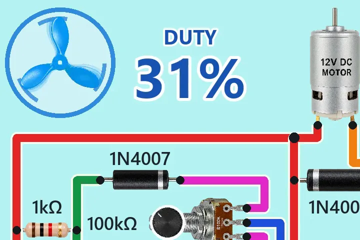 Same 555 timer + motor555 PWM speed controller for a 12 V DC motor with a TIP122A 555 timer makes the PWM that sets the speed of a small 12 V DC motor.
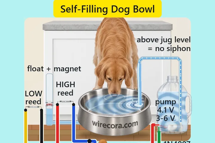 Next step: adds a pumpSelf-filling dog water bowl with a 555, a float and two reed switchesThe dog drinks the bowl down.
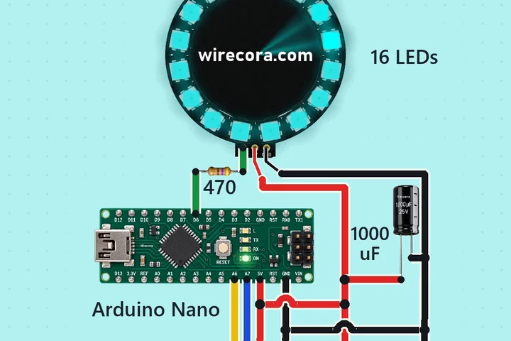 Something new: an ArduinoJoystick LED ring colour sweepTurn the joystick in a circle and the whole ring runs through the colour wheel.