555 PWM speed controller for a 12 V DC motor with a TIP122
A 555 timer makes the PWM that sets the speed of a small 12 V DC motor. Turn the 100 kohm pot and the duty cycle follows the knob, about 1 % to 99 %, while the frequency stays about constant at 127 to 132 Hz. The TIP122 switches the motor on for a longer or shorter part of every cycle, so the fan speeds up or slows down.
- 8 parts
- 8 wiring steps
- No code needed
- 12 V supply
Quick answer
The short version. Every pin is in the full wiring below.What you need
- NE555 timer
- TIP122 Darlington transistor
- 3 x 1N4007 diodes: two steering diodes and one flyback diode across the motor
- 2 x 1 kohm resistors
- 100 kohm linear pot
- 0.1 uF
- Small 12 V DC motor
- 12 V battery
How to wire it
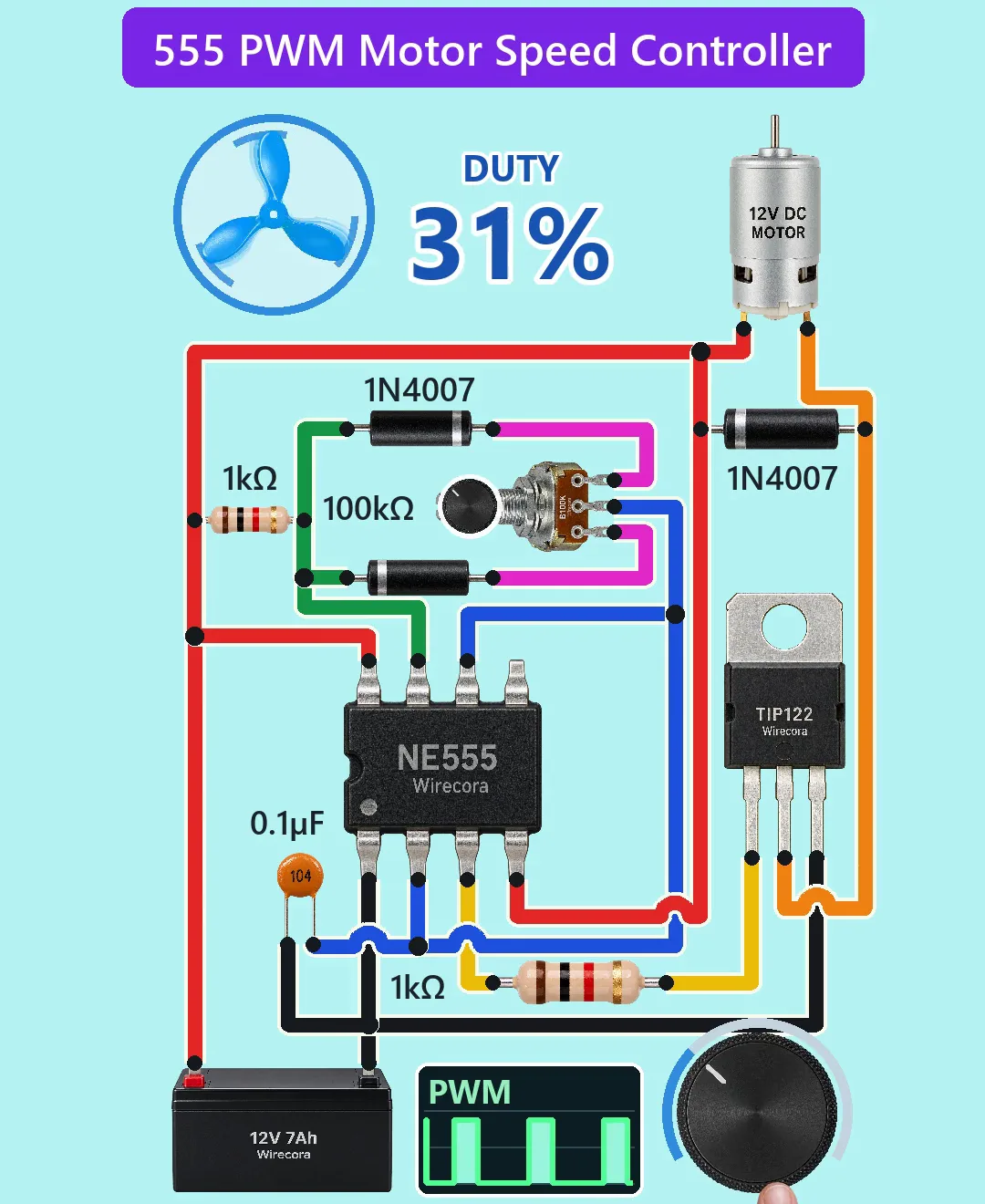
- 12 V plus to NE555 pin 8 (VCC) and pin 4 (RESET), to one 1 kohm resistor (R_A), to one motor terminal, and to the band (cathode) of the flyback diode.
- 12 V minus to pin 1 (GND), the TIP122 emitter and the 0.1 uF capacitor.
- The other end of R_A to pin 7 (DISCH), the anode of the first steering diode (D1) and the cathode of the second (D2).
- D1's cathode to one outer pot lug, D2's anode to the other outer pot lug.
- Pin 3 (OUT) to the second 1 kohm resistor, then to the TIP122 base.
- The motor's other terminal to the TIP122 collector and to the flyback diode's anode (band to plus).
- TIP122 legs from the front (marking side, legs down): base, collector, emitter, left to right.
- Swap the two outer pot wires to reverse the knob direction.
Before you power it: Everything here runs on 12 V DC from a small battery. Use a small motor, add a heatsink to the TIP122 if the motor draws more than about 1 A, and never wire a mains motor this way.
Parts list
- NE555 timer
- TIP122 Darlington transistor (TO-220)
- 3 x 1N4007 diodes: two steering diodes and one flyback diode across the motor
- 2 x 1 kohm resistors
- 100 kohm linear pot (B100K)
- 0.1 uF (104) ceramic capacitor, the timing capacitor
- Small 12 V DC motor
- 12 V battery (the Short draws a 12 V 7 Ah lead-acid)
Wiring, step by step
- 12 V plus to NE555 pin 8 (VCC) and pin 4 (RESET), to one 1 kohm resistor (R_A), to one motor terminal, and to the band (cathode) of the flyback diode.
- 12 V minus to pin 1 (GND), the TIP122 emitter and the 0.1 uF capacitor.
- The other end of R_A to pin 7 (DISCH), the anode of the first steering diode (D1) and the cathode of the second (D2).
- D1's cathode to one outer pot lug, D2's anode to the other outer pot lug. The pot's wiper goes to pins 2 and 6 (TRIG and THRES, tied together) and to the 0.1 uF capacitor.
- Pin 3 (OUT) to the second 1 kohm resistor, then to the TIP122 base.
- The motor's other terminal to the TIP122 collector and to the flyback diode's anode (band to plus).
- TIP122 legs from the front (marking side, legs down): base, collector, emitter, left to right. Pin 5 stays open.
- Swap the two outer pot wires to reverse the knob direction.
How it works
- The timing capacitor charges through R_A, D1 and the upper part of the pot, and discharges through the lower part of the pot, D2 and pin 7. Moving the wiper changes the high time and the low time but almost not their sum, so the duty cycle changes while the frequency stays about constant.
- In the simulation the duty runs from about 1 % to 99 % and never reaches 0 or 100 %. Over 2 % to 98 % of the knob the frequency stays between 127.3 and 132.3 Hz.
- Pin 3 drives the TIP122 base through 1 kohm, about 9 mA, a small share of the NE555's 200 mA limit.
- The flyback diode is essential. Without it the collector spiked to about 120 V in the simulation, above the TIP122's 100 V rating. With it the collector peaks at about 13 V.
- At full duty the motor takes about 1 A and the TIP122 dissipates about 1 W.
- In the model the motor does not start below about 8 % duty, because of friction.
What the video simplifies
- The fan is an icon beside the motor, not on its shaft. The fan speed comes from an illustrative 12 V motor model; a real motor differs.
- The PWM trace is a drawing, and the big knob stands for the pot's knob.
- The sound is synthesised.
- The decoupling capacitor is omitted and pin 5 is left open in the drawing. In a real build add 100 nF across pins 8 and 1, and optionally 10 nF on pin 5.
- Use a small 12 V motor only. Above about 1 A put the TIP122 on a heatsink; a stalled rotor (about 3.4 A) puts about 5.5 W into it, which needs a heatsink.
- The original video has no values and its wiring cannot be traced; this version was re-derived and checked.
- The NE555 and TIP122 models are fitted behavioural models, not vendor models. Simulated in ngspice, not measured on hardware.
You found this by searching. Here's the whole path.
- Read how it works
- See it work
- Build it
- Show it
Thirty seconds of video shows the circuit doing its job.
Everything here runs on 12 V DC from a small battery. Use a small motor, add a heatsink to the TIP122 if the motor draws more than about 1 A, and never wire a mains motor this way.
Built it, or stuck halfway? Post a photo in the Wirecora Discord. Questions get an answer every day.
What to build next
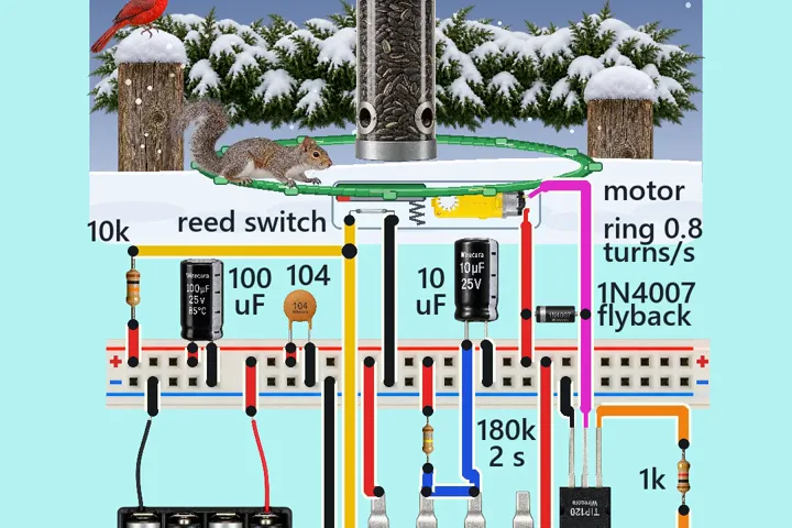 Same 555 timer + motorSpinning bird feeder perch that turns when a squirrel climbs onA squirrel hops onto the feeder's perch ring and the ring starts to turn.
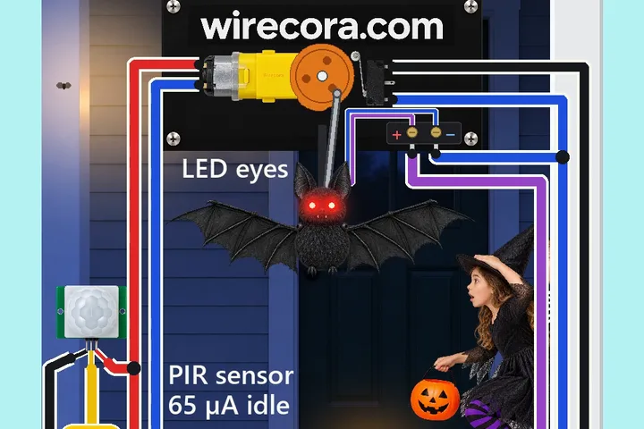 Next step: adds a PIR sensorFlapping porch bat with a motion sensor, a TIP120 and a TT gear motorTrick-or-treaters walk up to the door, a motion sensor sees them, and the big bat under the porch roof lights its red eyes and beats its wings, about two a second.
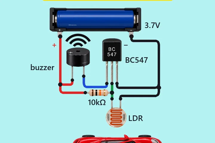 Something new: a light sensorLaser tripwire alarmA red laser shines on a light sensor and the buzzer stays quiet.