Laser tripwire alarm
A red laser shines on a light sensor and the buzzer stays quiet. Put a hand or a toy car in the beam and the buzzer sounds. Take it away and the buzzer goes quiet again.
- 7 parts
- 8 wiring steps
- No code needed
- 3.7 V supply
Quick answer
The short version. Every pin is in the full wiring below.What you need
- 3.7 V 18650 Li-ion cell in a holder
- Active buzzer, 3 to 5 V type
- BC547 NPN transistor
- 10 k ohm resistor, 1/4 W
- Light sensor
- Red laser module, 650 nm, under 5 mW, 3 to 5 V
- Jumper wires
How to wire it
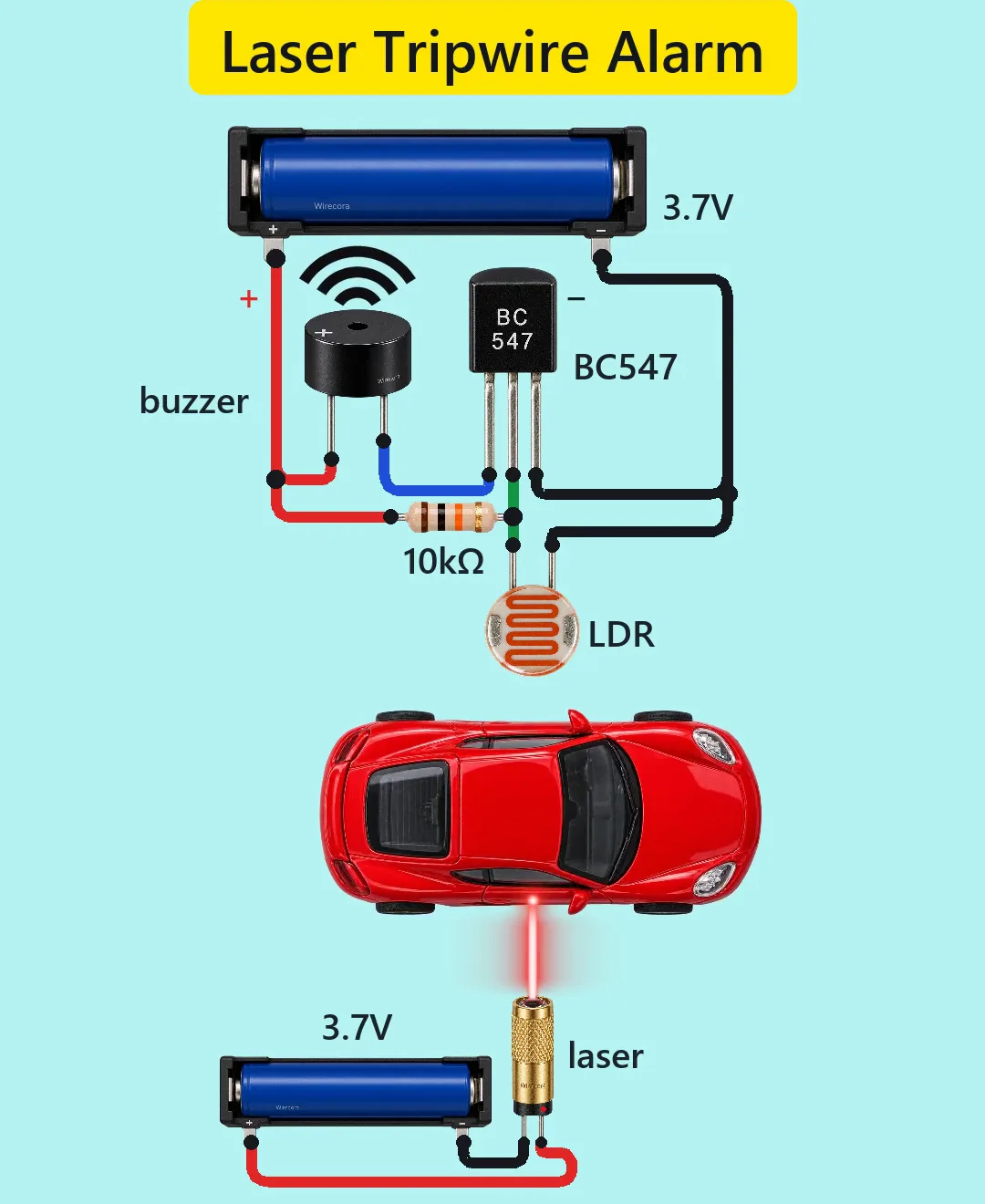
- Cell plus to the buzzer's plus leg.
- Buzzer's minus leg to the BC547's collector (C, the left leg).
- 10 k resistor from cell plus to the BC547's base (B, the middle leg).
- One LDR leg to the BC547's base (B).
- The other LDR leg to cell minus.
- BC547 emitter (E, the right leg) to cell minus.
- The laser module goes on its own cell: laser plus (red) to that cell's plus, laser minus (black) to that cell's minus.
- Point the laser at the LDR's face, so the beam lands on it.
Before you power it: Never look into a laser beam and never point it at anyone's eyes, at people, at vehicles or at aircraft; use a red module under 5 mW only. The alarm runs on a 3.7 V lithium cell: use a protected cell, never short its two terminals, and charge it only in a charger made for 18650 cells.
Parts list
- 3.7 V 18650 Li-ion cell in a holder (use a protected cell), for the alarm circuit
- Active buzzer, 3 to 5 V type (the Short assumes about 20 mA at 3.5 V; it has its own tone circuit inside and the + leg is the long one)
- BC547 NPN transistor (flat face toward you, legs down: C, B, E from left to right)
- 10 k ohm resistor, 1/4 W (brown, black, orange, gold)
- Light sensor (LDR, for example a GL5528), facing the laser
- Red laser module, 650 nm, under 5 mW, 3 to 5 V (about 30 mA), with its own 3.7 V 18650 cell and holder
- Jumper wires
Wiring, step by step
- Cell plus to the buzzer's plus leg. Cell plus is also the supply for the 10 k resistor.
- Buzzer's minus leg to the BC547's collector (C, the left leg).
- 10 k resistor from cell plus to the BC547's base (B, the middle leg).
- One LDR leg to the BC547's base (B). The 10 k resistor and the LDR meet on that leg.
- The other LDR leg to cell minus.
- BC547 emitter (E, the right leg) to cell minus.
- The laser module goes on its own cell: laser plus (red) to that cell's plus, laser minus (black) to that cell's minus. The laser's cell is not joined to the alarm circuit.
- Point the laser at the LDR's face, so the beam lands on it.
How it works
- While the beam lands on the LDR it has a low resistance (the Short assumes about 400 ohm). It pulls the BC547's base down to minus, to about 0.14 V. That is too low to switch the transistor on, so no current flows through the buzzer and it stays quiet.
- When a hand or a car cuts the beam, the LDR goes back to its room-light resistance (the Short assumes about 15 k ohm). Now the 10 k resistor wins: about 0.25 mA flows into the base, and the base sits at about 0.7 V.
- That small base current switches the BC547 fully on. About 19 mA flows from cell plus through the buzzer and the transistor to minus, with about 3.5 V across the buzzer, so it sounds. The transistor handles up to 100 mA, so it has plenty of room.
- The alarm starts when the LDR's resistance rises above about 1.94 k ohm. Move the hand or car out of the beam and the LDR drops low again, the base falls to 0.14 V and the buzzer stops.
What the video simplifies
- The red beam with its glow is drawn. A real laser beam is invisible in clean air, and you only see the dot where it lands.
- The hand and the toy car are props, and the buzzer reacts the instant the beam is cut. A real LDR is slower, about tens of milliseconds, and it can chatter when the beam is only partly blocked.
- The sounds in the Short are synthesised.
- The buzzer's 20 mA at 3.5 V and the LDR's 400 ohm under the laser spot are assumptions, not measurements. If your buzzer draws over about 27 mA, use a 4.7 k ohm resistor in place of the 10 k.
- The laser module is drawn without the little driver circuit inside it, and it is always on.
- Strong room light stops the alarm: above about 300 lux the unlit LDR falls below 2 k ohm and the buzzer never sounds. Put the LDR in a dark tube and aim the beam down the tube.
- The trip point moves a little with the cell's voltage (3.0 to 4.2 V), so a trimmer in place of the 10 k resistor helps you set it.
- This circuit was checked by simulation (ngspice) and against the datasheets, not built.
You found this by searching. Here's the whole path.
- Read how it works
- See it work
- Build it
- Show it
Thirty seconds of video shows the circuit doing its job.
Never look into a laser beam and never point it at anyone's eyes, at people, at vehicles or at aircraft; use a red module under 5 mW only. The alarm runs on a 3.7 V lithium cell: use a protected cell, never short its two terminals, and charge it only in a charger made for 18650 cells.
Built it, or stuck halfway? Post a photo in the Wirecora Discord. Questions get an answer every day.
What to build next
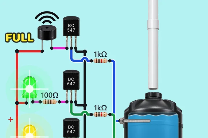 Same buzzerWater level indicator with a buzzerWater pours into the tank.
 Next step: adds a relayParcel alarm that keeps goingLift the parcel and a siren sounds with red and blue strobe flashes.
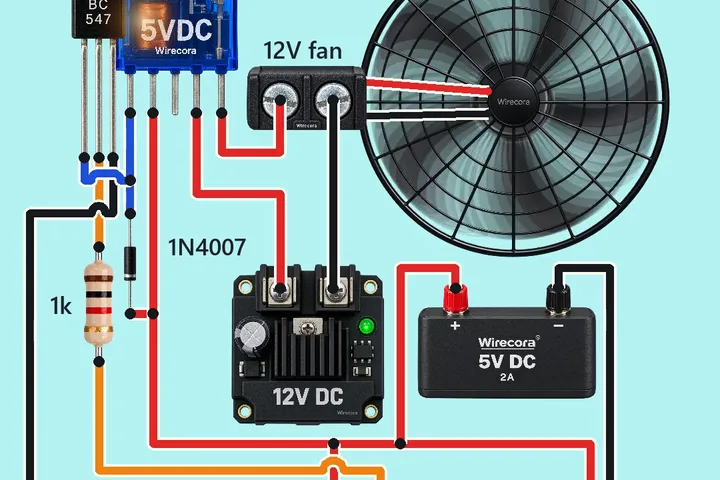 Something new: a relayAutomatic fan controller: NTC thermistor and LM358Touch the thermistor with something hot and the fan starts.