Automatic fan controller: NTC thermistor and LM358
Touch the thermistor with something hot and the fan starts. Take the heat away and the fan stops again. A 100 k NTC thermistor tells an LM358 chip how warm it is, the LM358 switches a BC547 transistor, and the transistor pulls in a relay that connects a 12 V fan.
- 12 parts
- 8 wiring steps
- No code needed
- 12 V supply
Quick answer
The short version. Every pin is in the full wiring below.What you need
- 100 k NTC thermistor
- LM358 dual op-amp, DIP-8, used as a comparator
- 10 k trimmer potentiometer
- BC547 NPN transistor
- 5 V relay, coil about 70 ohm
- 1N4007 diode across the relay coil
- 100 k resistor
- 4.7 k resistor, above the trimmer
- 1 k resistor
- 5 V DC power supply module
- 12 V DC power supply module
- 12 V DC fan
How to wire it
- 5 V supply plus to the relay coil pin CA, the LM358 pin 8, the top of the 100 k resistor, the top of the 4.7 k resistor, and the band (cathode) end of the 1N4007.
- 5 V supply minus to the BC547 emitter, LM358 pin 4 and pin 5, one leg of the NTC, and the bottom end of the trimmer.
- 100 k resistor bottom to the other NTC leg and to LM358 pin 2 (IN-).
- 4.7 k resistor bottom to the top end of the 10 k trimmer.
- LM358 pin 1 (OUT) to the 1 k resistor, and the 1 k resistor to the BC547 base.
- BC547 collector to the relay coil pin CB, and to the other end of the 1N4007 (the anode, the end without the band).
- LM358 pin 6 to pin 7, and pin 5 to ground.
- 12 V supply plus to the relay COM contact.
Before you power it: The 5 V part and the 12 V fan part are both low voltage. Never switch mains with this build. Make sure the fan and its current fit within what your relay contacts are rated for, and use something hot only with care: do not touch the thermistor with a soldering iron tip or a lighter without holding it safely.
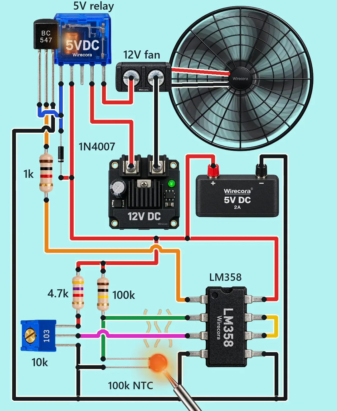
Parts list
- 100 k NTC thermistor (100 k at 25 C, beta 3950 K; its resistance falls as it gets hot)
- LM358 dual op-amp, DIP-8, used as a comparator
- 10 k trimmer potentiometer (marking 103), to set the temperature
- BC547 NPN transistor (TO-92)
- 5 V relay, coil about 70 ohm (SRD-05VDC style), with COM, NO and NC contacts
- 1N4007 diode across the relay coil
- 100 k resistor, in the divider above the thermistor (brown, black, yellow)
- 4.7 k resistor, above the trimmer (yellow, violet, red)
- 1 k resistor, between the LM358 output and the BC547 base (brown, black, red)
- 5 V DC power supply module
- 12 V DC power supply module
- 12 V DC fan
Wiring, step by step
- 5 V supply plus to the relay coil pin CA, the LM358 pin 8, the top of the 100 k resistor, the top of the 4.7 k resistor, and the band (cathode) end of the 1N4007.
- 5 V supply minus to the BC547 emitter, LM358 pin 4 and pin 5, one leg of the NTC, and the bottom end of the trimmer. All grounds are joined.
- 100 k resistor bottom to the other NTC leg and to LM358 pin 2 (IN-). This joint is the temperature voltage.
- 4.7 k resistor bottom to the top end of the 10 k trimmer. The trimmer's middle lug (the wiper) goes to LM358 pin 3 (IN+). This is the temperature you set.
- LM358 pin 1 (OUT) to the 1 k resistor, and the 1 k resistor to the BC547 base. Seen with the flat face toward you and the legs down, the BC547 legs are collector, base, emitter from left to right.
- BC547 collector to the relay coil pin CB, and to the other end of the 1N4007 (the anode, the end without the band). The diode catches the voltage kick when the coil switches off.
- LM358 pin 6 to pin 7, and pin 5 to ground. The second amplifier in the chip is not used, and this keeps it quiet.
- 12 V supply plus to the relay COM contact. Relay NO contact to the fan's plus terminal. Fan minus terminal to 12 V supply minus. The relay is the only link between the 5 V part and the 12 V part.
How it works
- The 100 k resistor and the NTC form a voltage divider on 5 V. Cold, the NTC is about 100 k and the divider voltage on LM358 pin 2 is about 2.5 V. As the NTC gets hot its resistance falls and that voltage falls.
- The trimmer, behind the 4.7 k resistor, gives pin 3 a fixed voltage you choose. With the trimmer at 38 % that is about 1.29 V, and the divider reaches 1.29 V when the NTC is about 51 C.
- The LM358 compares the two. Cold, pin 2 is higher than pin 3 and the output is low. When the NTC passes the trip point, pin 2 drops below pin 3 and the output goes high, about 3.5 V.
- Through the 1 k resistor that gives the BC547 base about 2.8 mA. The transistor switches on fully and the relay coil gets about 69 mA, enough to pull the relay in.
- The relay closes COM to NO and the 12 V fan runs. When the NTC cools, the LM358 output goes low, the transistor turns off, the relay lets go and the fan stops.
What the video simplifies
- The heating and cooling of the thermistor is sped up for the video. A real thermistor cools much more slowly.
- The glowing soldering iron, the orange thermistor, the heat lines, the relay click flash and the sound are effects, not parts of the circuit.
- The fan spins slower on screen than a real one, because that reads better in a video.
- There is no hysteresis. A real thermostat adds a resistor from the LM358 output back to pin 3, so it switches on and off at two slightly different temperatures, about 2 to 5 C apart, and does not chatter near the trip point.
- The relay is drawn as a bare 5 V relay with five pins in a row. A real SRD-05VDC has its pins staggered, and the NC contact is left unused.
- The original Short switched mains through a 5 V relay. This one uses a 12 V DC fan, which is safer to build and test.
- This circuit was checked by simulation and datasheets, not built.
You found this by searching. Here's the whole path.
- Read how it works
- See it work
- Build it
- Show it
Thirty seconds of video shows the circuit doing its job.
The 5 V part and the 12 V fan part are both low voltage. Never switch mains with this build. Make sure the fan and its current fit within what your relay contacts are rated for, and use something hot only with care: do not touch the thermistor with a soldering iron tip or a lighter without holding it safely.
Built it, or stuck halfway? Post a photo in the Wirecora Discord. Questions get an answer every day.
What to build next
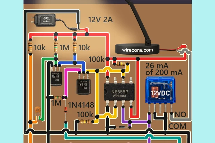 Same relayClap switch lamp with a 555Clap once and the desk lamp turns on.
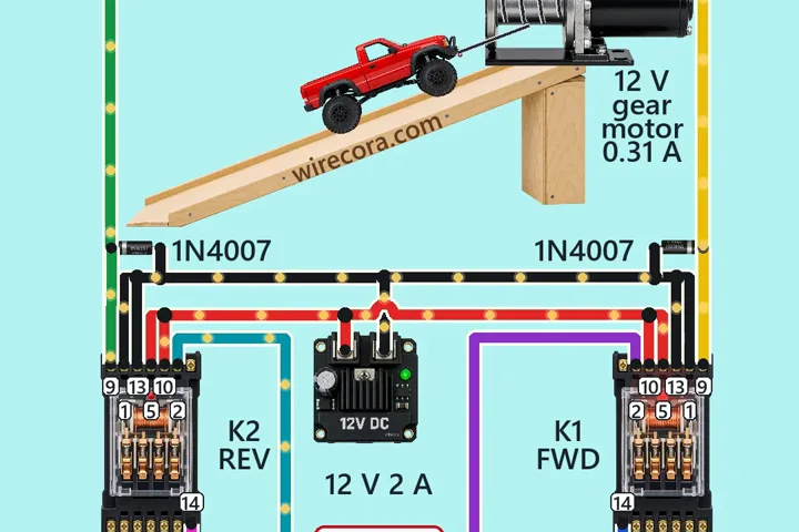 Next step: adds a motorWinch with an interlockHold FORWARD and the winch pulls the car up the ramp.
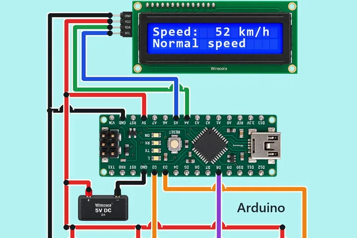 Something new: an ArduinoVehicle speed detector: two IR sensors, Arduino Nano and an LCDA car drives past two IR sensors that stand 1 metre apart.