Vehicle speed detector: two IR sensors, Arduino Nano and an LCD
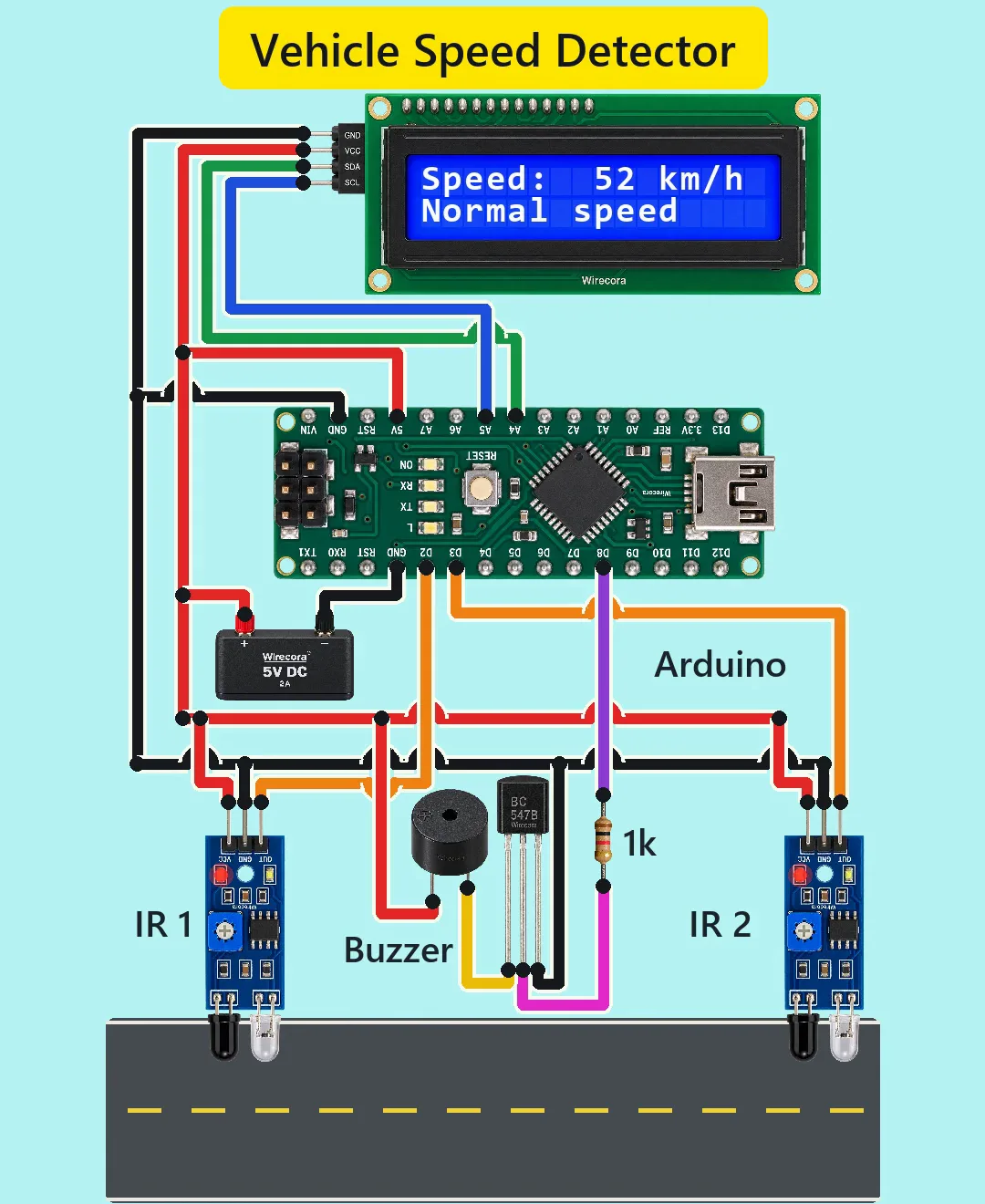
A car drives past two IR sensors that stand 1 metre apart. The Arduino Nano times how long the car takes to get from the first sensor to the second and shows the speed on a 16x2 LCD. A slow car gets "Normal speed". A car over 100 km/h gets "Over speeding!" and the buzzer beeps.
- 8 parts
- 7 wiring steps
- Arduino code
- 5 V supply
Quick answer
The short version. Every pin is in the full wiring below.What you need
- Arduino Nano
- 16x2 LCD with an I2C backpack
- FC-51 IR obstacle sensor module, two of them
- 5 V active buzzer
- BC547B NPN transistor
- 1 k resistor, 1/4 W
- Regulated 5 V 2 A supply
- Jumper wires
How to wire it
- Supply plus (red) to the Nano 5V pin, and by the red wires on to the LCD's VCC, both sensors' VCC and the buzzer's plus pin.
- Supply minus (black) to the Nano's GND pin, and by the black wires on to the LCD's GND, both sensors' GND and the BC547's emitter (E).
- LCD SDA (green) to Nano A4.
- First IR sensor OUT to Nano D2.
- Nano D8 to one end of the 1 k resistor.
- BC547 collector (C, the left leg) to the buzzer's minus pin.
- Do not plug in USB while the supply feeds the 5V pin.
Before you power it: Everything runs on 5 V from a regulated supply. Feed only a good 5 V to the Nano's 5V pin, and never plug in USB while it is connected. Keep the sensors and wires out of the road; this is a model, not something to put beside real traffic.
Parts list
- Arduino Nano (5 V, ATmega328P)
- 16x2 LCD with an I2C backpack (PCF8574; four pins: GND, VCC, SDA, SCL)
- FC-51 IR obstacle sensor module, two of them (three pins: VCC, GND, OUT; the output goes LOW when it sees something; they see only about 2 to 30 cm)
- 5 V active buzzer (4 to 8 V, up to 30 mA; the longer pin is plus)
- BC547B NPN transistor (flat face toward you, the legs are C, B, E from left to right)
- 1 k resistor, 1/4 W (brown, black, red, gold), in the transistor's base line
- Regulated 5 V 2 A supply
- Jumper wires, and a 1 metre stretch of road with the sensors at each end
Wiring, step by step
- Supply plus (red) to the Nano 5V pin, and by the red wires on to the LCD's VCC, both sensors' VCC and the buzzer's plus pin.
- Supply minus (black) to the Nano's GND pin, and by the black wires on to the LCD's GND, both sensors' GND and the BC547's emitter (E). The Nano's two GND pins are the same piece of copper.
- LCD SDA (green) to Nano A4. LCD SCL (blue) to Nano A5.
- First IR sensor OUT to Nano D2. Second IR sensor OUT to Nano D3.
- Nano D8 to one end of the 1 k resistor. The other end of the resistor to the BC547's base (B, the middle leg).
- BC547 collector (C, the left leg) to the buzzer's minus pin. The buzzer's plus pin stays on +5 V.
- Do not plug in USB while the supply feeds the 5V pin. Upload the sketch first, unplug USB, then connect the supply.
How it works
- With no car, both sensor outputs sit HIGH at about 5 V and the LCD reads "No car found" and "Limit 100 km/h".
- When the car's front passes the first sensor, its OUT falls LOW on D2. That triggers an interrupt and the sketch stores the time in microseconds. The second sensor does the same on D3.
- The sketch takes the time between the two, dt, and works out speed in km/h = 3600 x 1000 mm / dt in microseconds, using the 1000 mm spacing. 69.2 ms between the sensors gives 52 km/h, and 22.5 ms gives 160 km/h.
- Up to 100 km/h the LCD shows the speed and "Normal speed" for 2 seconds. Above 100 km/h it shows "Over speeding!" and pin D8 goes HIGH and LOW six times, 200 ms on and 133 ms off.
- D8 gives the BC547 about 4 mA through the 1 k resistor, which switches the transistor fully on. It lets the buzzer's current of up to 30 mA run to ground, so the Nano pin never has to carry it. Then the screen goes back to "No car found".
The code: speed_detector.ino
The Arduino code for this circuit is in the Wirecora Discord, in the channel #arduino-code (owner’s choice, 14 October 2026: the code lives where you can ask about it). It is a plain .ino file you can download there.
The sketch the Short was animated from. It uses the LiquidCrystal_I2C library (Sketch, Include Library, Manage Libraries) and has not been run on a real board. If the LCD stays blank, change the address 0x27 to 0x3F, which some backpacks use.
What the video simplifies
- The cars in the Short are drawn 6 times slower than the timed values (the LCD and the buzzer run in real time).
- The FC-51 sensors only see about 2 to 30 cm, so this is a model or test-track setup, not sensors beside a real road. The 1 metre spacing is between the two sensors.
- IR light is invisible; the only sign of a detection is a light on the sensor module. Which of the two small lights on the module marks a detection is an assumption in the Short.
- The buzzer sound is made up for the video.
- The 135 mA the whole circuit draws is an estimate, well under what the 2 A supply can give.
- The original viral video drives the buzzer straight from a Nano pin. This one adds the BC547 and its 1 k resistor, and shows a real regulated 5 V supply.
- This circuit was checked by simulation (ngspice), against the datasheets and by working through the sketch's maths, not built.
You found this by searching. Here's the whole path.
- Read how it works
- See it work
- Build it
- Show it
Thirty seconds of video shows the circuit doing its job.
Everything runs on 5 V from a regulated supply. Feed only a good 5 V to the Nano's 5V pin, and never plug in USB while it is connected. Keep the sensors and wires out of the road; this is a model, not something to put beside real traffic.
Built it, or stuck halfway? Post a photo in the Wirecora Discord. Questions get an answer every day.
What to build next
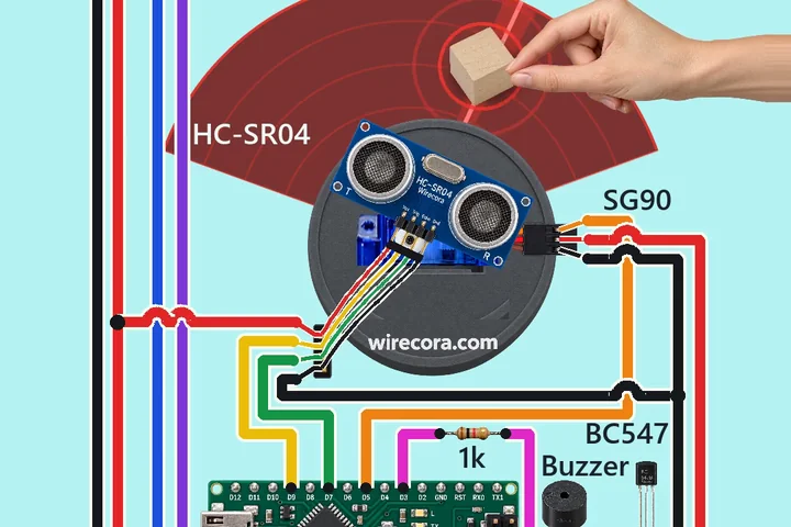 Same Arduino + buzzerArduino radar guard with an HC-SR04 and a servoAn ultrasonic sensor on a servo sweeps from side to side.
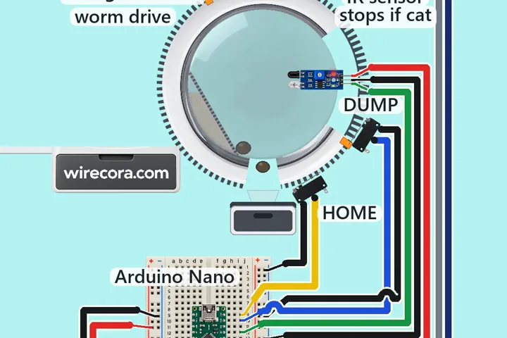 Next step: adds a motorSelf-cleaning litter boxWhen the cat has been out of the drum for seven minutes, an Arduino Nano turns the drum half a turn.
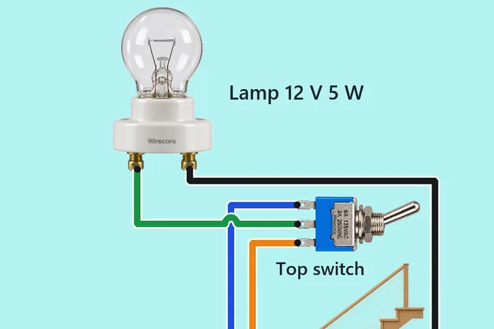 Something new: a lampStaircase light: two switches, one lampFlip either of two switches and the lamp changes: on becomes off, off becomes on.