Winch with an interlock
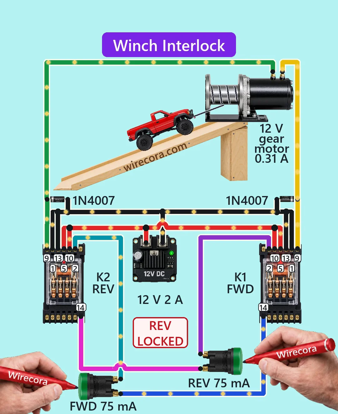
Hold FORWARD and the winch pulls the car up the ramp. Press REVERSE at the same time and nothing happens. Let go and the winch stops; hold REVERSE and the car rolls back down while FORWARD is locked out.
- 6 parts
- 6 wiring steps
- No code needed
- 12 V supply
Quick answer
The short version. Every pin is in the full wiring below.What you need
- 12 V 2 A DC power supply
- 12 V four-pole relay with built-in LED and coil diode
- Normally open push button
- 12 V gear-motor winch
- 1N4007 diode
- A car, a ramp and a cord for the winch drum
How to wire it
- Supply plus to terminals 5 and 10 of both relays.
- Supply minus to terminals 1 and 13 of both relays.
- Terminal 9 of relay K1 (forward) to one winch terminal, and terminal 9 of relay K2 (reverse) to the other.
- 1N4007 from supply minus (anode) to each winch terminal (band on the winch terminal).
- Terminal 2 of K2 to one side of the FWD button, and the other side of FWD to terminal 14 of K1.
- Terminal 2 of K1 to one side of the REV button, and the other side of REV to terminal 14 of K2.
Before you power it: All 12 V DC. Keep hands and clothing away from the winch drum and cord, and wire the limit switches a real winch needs before using it on anything that can fall.
Parts list
- 12 V 2 A DC power supply
- 12 V four-pole relay with built-in LED and coil diode (Omron MY4N-D2 type, coil 75 mA), two of them, each on its own 14-pin socket
- Normally open push button, two of them, marked FWD and REV (each carries only the 75 mA coil current)
- 12 V gear-motor winch (about 0.31 A pulling the car in the Short, about 1.2 A if stalled; these figures are assumed)
- 1N4007 diode, two of them, one from supply minus to each motor lead
- A car, a ramp and a cord for the winch drum
Wiring, step by step
- Supply plus to terminals 5 and 10 of both relays. Terminal 5 is the normally open contact of pole 1, terminal 10 is the common of pole 2.
- Supply minus to terminals 1 and 13 of both relays. Terminal 1 is the normally closed contact of pole 1, terminal 13 is the coil minus on an MY4N-D2.
- Terminal 9 of relay K1 (forward) to one winch terminal, and terminal 9 of relay K2 (reverse) to the other. Terminal 9 is the common of pole 1.
- 1N4007 from supply minus (anode) to each winch terminal (band on the winch terminal). Do not put a diode across the motor itself: in one direction it would short the supply through the contacts.
- Terminal 2 of K2 to one side of the FWD button, and the other side of FWD to terminal 14 of K1. Terminal 14 is the coil plus on an MY4N-D2.
- Terminal 2 of K1 to one side of the REV button, and the other side of REV to terminal 14 of K2.
How it works
- Each relay's coil is fed from supply plus through the other relay's terminals 10 and 2 (its pole 2 common and normally closed contact, joined while that relay is out), then through its own button.
- Hold FWD: the coil of K1 gets 12 V and K1 pulls in about 20 ms later. Its pole 1 puts 12 V on one winch terminal and the other stays at minus, so the winch pulls the car up.
- While K1 is in, its terminal 2 is open. Press REV now and K2's coil has no feed, so nothing moves. The same lock works the other way round for K2.
- Let go and the relay drops, both winch terminals go to minus and the winch stops. Hold REV: K2 pulls in, the winch turns the other way and FWD is locked out.
- The two relays can never be in at the same time. Even if both were, both winch terminals would be at plus and nothing would short.
What the video simplifies
- There is no STOP button and no latch: this is hold-to-run. Let go of one button and press the other at once and the winch reverses about 40 ms later at about 2 A for a moment, more than the relay contacts are rated for (1.5 A inductive at 30 V DC). The interlock does not prevent that, so pause before you reverse.
- The winch figures (60 rpm, 0.1 A at no load, 1.2 A at stall), the car weight and the ramp are assumed. The car staying put on the ramp when the winch stops assumes a self-locking gearbox or a brake.
- The drawn socket uses our own tidy terminal order. A real socket orders its terminals differently, so wire by the numbers printed on the relay, and check the coil polarity printed on yours (a reverse-coil type has plus and minus the other way round). Wired the wrong way round, the built-in coil diode shorts the supply when you press the button.
- The right-hand relay is the same picture turned over, so its terminals face the other way. The parts are not drawn to one scale, and the REV LOCKED and FWD LOCKED labels, the LED glow and the moving dots are visual aids.
- A real winch would also have limit switches in series with each coil. None are drawn.
- This circuit was checked by calculation and datasheet figures, not built.
You found this by searching. Here's the whole path.
- Read how it works
- See it work
- Build it
- Show it
Next: see it work
Thirty seconds of video shows the circuit doing its job.
Then build it
All 12 V DC. Keep hands and clothing away from the winch drum and cord, and wire the limit switches a real winch needs before using it on anything that can fall.
Then show it
Built it, or stuck halfway? Post a photo in the Wirecora Discord. Questions get an answer every day.
What to build next
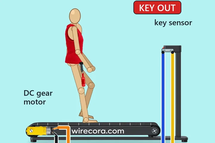 Same relay + motorTreadmill safety key stop with an Arduino Nano, a reed switch and a 5 V relayA runner jogs on a small model treadmill with a red magnet key clipped from their top to the console.
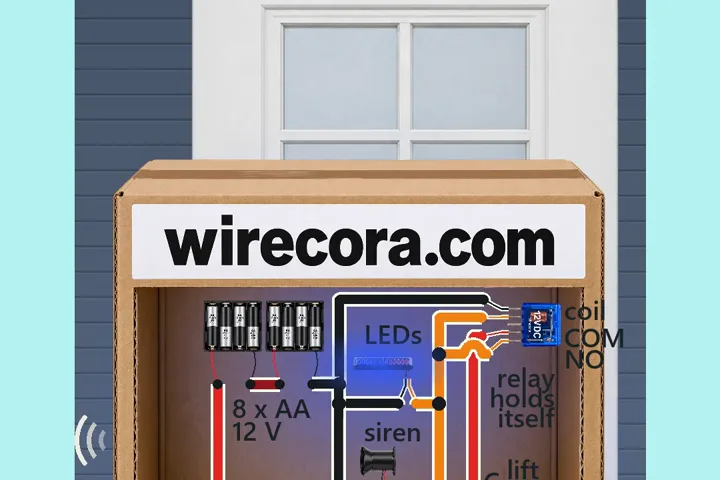 Next step: adds a buzzerParcel alarm that keeps goingLift the parcel and a siren sounds with red and blue strobe flashes.
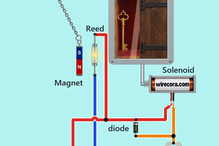 Something new: a reed switchMagnet-key hatchA magnet on a chain swings up beside a glass reed switch.