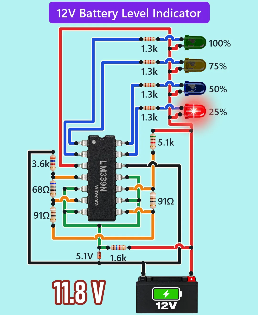
12 V battery level indicator with four LEDs
The battery's voltage falls and the four LEDs go out from the top: green (100 %) first, then yellow, blue and red (25 %). When the voltage rises again they light from the bottom up, red first. An LM339 chip compares four slices of the battery voltage with a steady 5.1 V and switches one LED for each. In the Short the number beside the battery drops from 12.8 V to 11.6 V and back.
- 11 parts
- 9 wiring steps
- No code needed
- 12 V supply
Quick answer
The short version. Every pin is in the full wiring below.What you need
- 12 V lead-acid battery
- LM339 quad comparator chip, 14 pins
- 5.1 V zener diode
- 1.6 k resistor, 1/4 W, in series with the zener
- 5.1 k resistor, 1/4 W, top of the voltage ladder
- 91 ohm resistor
- 68 ohm resistor, 1/4 W, in the voltage ladder
- 3.6 k resistor
- 5 mm LED, four of them: green
- 1.3 k resistor
- Jumper wires
How to wire it
- Battery plus to LM339 pin 3 (V+).
- Ladder: 5.1 k from battery plus to the first tap, then 91 ohm, 91 ohm, 68 ohm and 3.6 k in a chain down to battery minus.
- Tap under the 5.1 k to LM339 pin 10, the tap under the next 91 ohm to pin 8, the tap under the second 91 ohm to pin 6, and the tap under the 68 ohm (above the 3.6 k) to pin 4.
- Zener: its band end (cathode) to the reference line, its other end to battery minus.
- 1.6 k from battery plus to the zener's band end.
- Reference line to LM339 pins 5, 7, 9 and 11, the four plus inputs.
- Each LED's longer leg (anode) to battery plus.
- The other end of each 1.3 k to an output pin: the green (100 %) LED's resistor to pin 2, the yellow (75 %) to pin 1, the blue (50 %) to pin 14 and the red (25 %) to pin 13.
- Some makers print the names of channels 1 and 2 swapped.
Before you power it: Everything runs on a 12 V battery. A lead-acid battery can give a very large current, so put a fuse in the plus lead and a switch in the circuit, and take care that the battery's terminals never touch metal.
Parts list
- 12 V lead-acid battery (the circuit reads 11.6 to 12.8 V in the Short)
- LM339 quad comparator chip, 14 pins (DIP-14)
- 5.1 V zener diode (BZX55C5V1 type) as the steady reference
- 1.6 k resistor, 1/4 W, in series with the zener
- 5.1 k resistor, 1/4 W, top of the voltage ladder
- 91 ohm resistor, 1/4 W, two of them in the voltage ladder
- 68 ohm resistor, 1/4 W, in the voltage ladder
- 3.6 k resistor, 1/4 W, bottom of the voltage ladder
- 5 mm LED, four of them: green (100 %), yellow (75 %), blue (50 %) and red (25 %)
- 1.3 k resistor, 1/4 W, four of them, one in series with each LED
- Jumper wires
Wiring, step by step
- Battery plus to LM339 pin 3 (V+). Battery minus to LM339 pin 12 (GND).
- Ladder: 5.1 k from battery plus to the first tap, then 91 ohm, 91 ohm, 68 ohm and 3.6 k in a chain down to battery minus. The chain makes four taps, the points between the resistors.
- Tap under the 5.1 k to LM339 pin 10, the tap under the next 91 ohm to pin 8, the tap under the second 91 ohm to pin 6, and the tap under the 68 ohm (above the 3.6 k) to pin 4. These are the four minus inputs.
- Zener: its band end (cathode) to the reference line, its other end to battery minus. Reverse biased, it holds about 5.1 V.
- 1.6 k from battery plus to the zener's band end. This resistor feeds the zener its current.
- Reference line to LM339 pins 5, 7, 9 and 11, the four plus inputs.
- Each LED's longer leg (anode) to battery plus. Its short leg (cathode) goes to one 1.3 k resistor.
- The other end of each 1.3 k to an output pin: the green (100 %) LED's resistor to pin 2, the yellow (75 %) to pin 1, the blue (50 %) to pin 14 and the red (25 %) to pin 13.
- Some makers print the names of channels 1 and 2 swapped. Go by the pin numbers: pin 2 pairs with inputs 4 and 5, and pin 1 with inputs 6 and 7. The result is the same.
How it works
- The ladder of five resistors splits the battery voltage into four slices. Each tap sits at a fixed fraction of the battery voltage, so it rises and falls with the battery.
- The zener and its 1.6 k give a steady 5.1 V (5.07 to 5.09 V over the range shown) whatever the battery does. Each comparator checks whether its tap is above that reference.
- While a tap is above the reference, the comparator's output pulls down to ground. Current then flows from battery plus through the LED and its 1.3 k to the output, and the LED lights at about 7 to 8 mA.
- When the battery falls below a level, that tap drops below the reference, the output lets go and its LED goes out. The levels are 12.65 V for green, 12.4 V for yellow, 12.1 V for blue and 11.8 V for red, so the top LED goes out first.
- When the battery rises, the same levels are crossed upwards and the LEDs light from the bottom. There is no hysteresis, so an LED can flicker if the battery sits right at a level.
What the video simplifies
- The voltage falls from 12.8 V to 11.6 V in about a second and a half. A real battery takes hours, and the recharge in the Short is also sped up. A charging battery shows 13 to 14.4 V; the number in the Short is the rested voltage.
- Voltage only roughly shows charge, and only for a rested 12 V lead-acid battery (4 to 24 hours with no load or charger). Published charts differ by about 0.25 V, so the levels are approximate.
- The values are the nominal ones. The 5.1 V zener can be off by 6 percent, which moves all four levels together by up to about 0.75 V. A real build needs a trimmer (not drawn) set against a bench supply, and 1 percent resistors.
- The LED glow, the equal LED brightness, the sound and the part sizes are for the video.
- No switch is drawn. The circuit takes 6 to 39 mA from the battery all the time, so a real build needs one. No reverse-polarity or surge protection is drawn either.
- The LM339 is rated 0 to 70 degrees C, so it is not a part for under a car's bonnet.
- The LED voltages are typical values, not read from a datasheet. They do not change the levels.
- The popular version of this video wires four LEDs with 1 k resistors straight across the battery, so all four LEDs are always lit. This one measures the voltage.
- This circuit was checked by simulation (ngspice) and against the datasheets, not built.
You found this by searching. Here's the whole path.
- Read how it works
- See it work
- Build it
- Show it
Thirty seconds of video shows the circuit doing its job.
Everything runs on a 12 V battery. A lead-acid battery can give a very large current, so put a fuse in the plus lead and a switch in the circuit, and take care that the battery's terminals never touch metal.
Built it, or stuck halfway? Post a photo in the Wirecora Discord. Questions get an answer every day.
What to build next
 Similar partsParcel alarm that keeps goingLift the parcel and a siren sounds with red and blue strobe flashes.
 Something new: an ArduinoFloor mopping robot: Arduino Nano, HC-SR04 and L298NThe robot drives over a hard floor, mists a little water and wipes it with a cloth pad.
 Similar partsHelmet that closes its own visorYou lower the helmet onto your head and the visor swings down by itself.