Floor mopping robot: Arduino Nano, HC-SR04 and L298N
The robot drives over a hard floor, mists a little water and wipes it with a cloth pad. When the wall in front of it is closer than 15 cm, it stops, backs up, turns 90 degrees, steps one lane over and turns again. Then it mops the next stripe back the other way.
- 11 parts
- 11 wiring steps
- Arduino code
- 7.4 V supply
Quick answer
The short version. Every pin is in the full wiring below.What you need
- Arduino Nano
- HC-SR04 ultrasonic distance sensor
- L298N motor driver module
- TT gear motor, two of them
- 5 V mini water pump
- TIP120 transistor
- 1k resistor
- 1N4007 diode across the pump
- LM2596 buck converter module
- 7.4 V battery pack: two 18650 protected cells in series in a holder with a switch
- A fuse in the pack's plus lead
How to wire it
- Pack plus to the L298N 12V screw and to the LM2596 IN+.
- Set the LM2596 to 5.0 V with a meter before you connect anything else to it.
- LM2596 OUT+ to a 5 V rail.
- Nano GND and HC-SR04 GND to ground.
- HC-SR04 TRIG to Nano A5, and HC-SR04 ECHO to Nano A4.
- Nano D10 to L298N ENA, D9 to IN1, D8 to IN2, D7 to IN3, D6 to IN4 and D5 to ENB.
- L298N OUT1 and OUT2 to the right motor.
- Nano D4 to one end of the 1k resistor.
- TIP120 collector (C) to the pump minus.
- 1N4007 across the pump: its band (cathode) on the pump plus, the other end on the pump minus.
- Switch the pack off before you plug USB into the Nano to upload the sketch, because the Nano's 5V pin is fed by the LM2596.
Before you power it: The pack is 7.4 V and two 18650 cells can deliver a lot of current, so use protected cells and put a fuse in the plus lead. Use it on sealed hard floors only, keep the water tank away from the boards and the pack, and switch the pack off before you plug in USB.
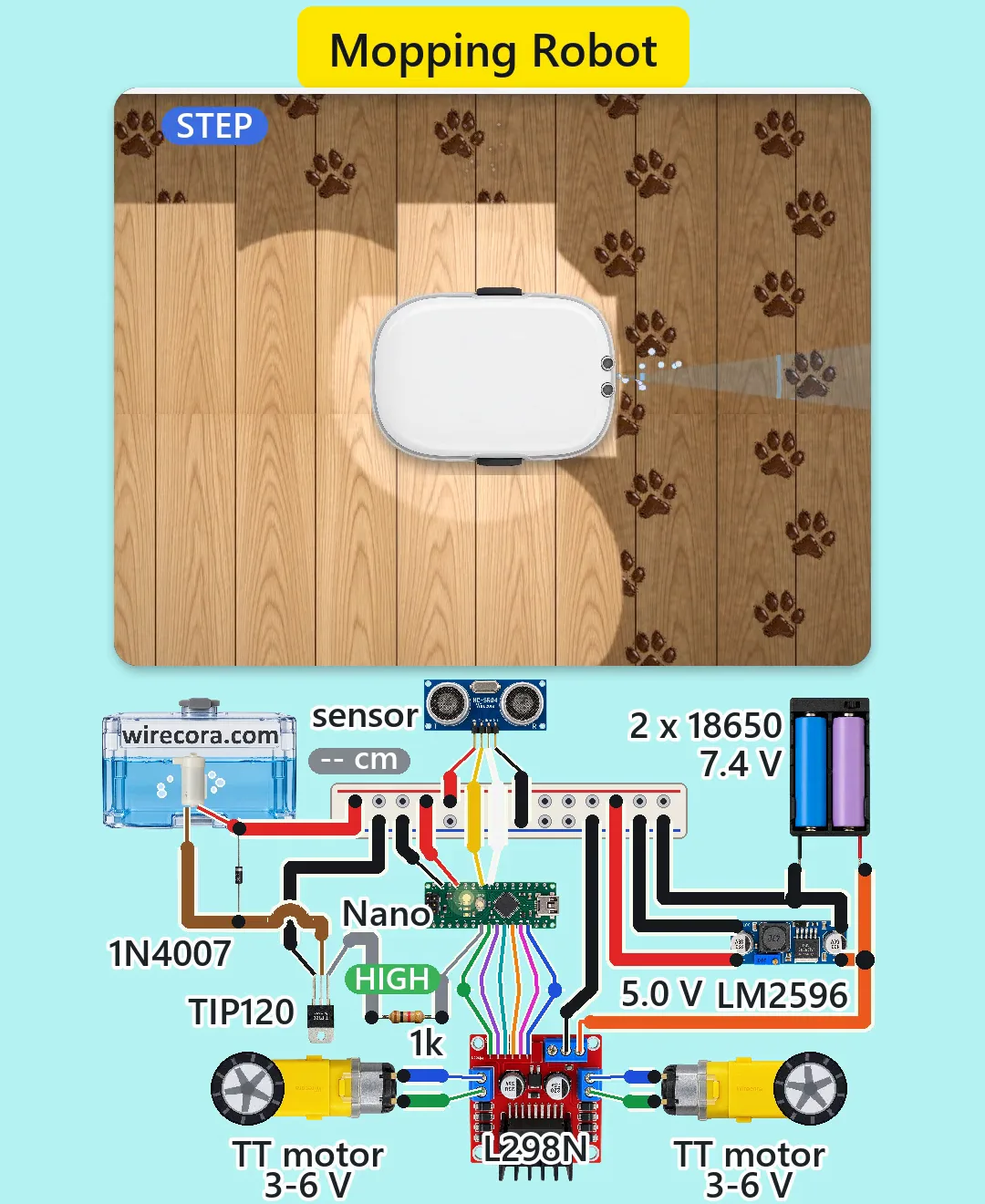
Parts list
- Arduino Nano (5 V)
- HC-SR04 ultrasonic distance sensor (5 V, about 15 mA; pins VCC, TRIG, ECHO, GND)
- L298N motor driver module (5 to 35 V motor supply, 2 A per channel)
- TT gear motor, two of them (3 to 6 V), one for each wheel
- 5 V mini water pump, in a small water tank, with a short hose to a nozzle at the front
- TIP120 transistor (Darlington) that switches the pump
- 1k resistor, 1/4 W, between Nano D4 and the TIP120 base
- 1N4007 diode across the pump
- LM2596 buck converter module (set to 5.0 V)
- 7.4 V battery pack: two 18650 protected cells in series in a holder with a switch
- A fuse in the pack's plus lead, a cloth pad, jumper wires and a breadboard strip or rail for the 5 V and ground lines
Wiring, step by step
- Pack plus to the L298N 12V screw and to the LM2596 IN+. Pack minus to the LM2596 IN-, the L298N GND screw and every other ground.
- Set the LM2596 to 5.0 V with a meter before you connect anything else to it. LM2596 OUT- goes to ground.
- LM2596 OUT+ to a 5 V rail. From that rail: Nano 5V pin, HC-SR04 VCC and the pump plus. Leave the Nano VIN pin empty.
- Nano GND and HC-SR04 GND to ground.
- HC-SR04 TRIG to Nano A5, and HC-SR04 ECHO to Nano A4.
- Nano D10 to L298N ENA, D9 to IN1, D8 to IN2, D7 to IN3, D6 to IN4 and D5 to ENB. Take the two jumper caps off ENA and ENB, keep the 5 V jumper on and leave the +5V screw empty.
- L298N OUT1 and OUT2 to the right motor. L298N OUT3 and OUT4 to the left motor, which is mounted facing outward.
- Nano D4 to one end of the 1k resistor. The other end of the 1k goes to the TIP120 base (B).
- TIP120 collector (C) to the pump minus. TIP120 emitter (E) to ground.
- 1N4007 across the pump: its band (cathode) on the pump plus, the other end on the pump minus. It catches the voltage kick when the pump switches off.
- Switch the pack off before you plug USB into the Nano to upload the sketch, because the Nano's 5V pin is fed by the LM2596.
How it works
- The HC-SR04 sends a short burst of ultrasound when TRIG is pulsed high for 10 microseconds. ECHO stays high until the sound comes back, and the sketch turns that time into centimetres by dividing the microseconds by 58.
- While the wall reads 15 cm or more, the sketch calls go(150, 150): both motors drive forward at 150 out of 255, and the robot reads the sensor about 15 times a second.
- Every 750 ms the sketch sets D4 high for a short pulse. About 3.5 mA flows into the TIP120 base through the 1k, the transistor turns on, and the pump gets about 4.1 V and mists a little water in front of the pad. When D4 goes low the 1N4007 absorbs the pump's kick.
- At the first reading under 15 cm, the pump is switched off and the sketch brakes for 100 ms, backs up for 200 ms (about 6 cm), turns on the spot for 450 ms (about 90 degrees) with one wheel forward and one back, drives one lane over for 650 ms, turns another 450 ms the same way and brakes.
- The sketch swaps the turn direction each time (right, then left, then right), so the robot mops the floor in stripes, back and forth.
- The motors get about 3.2 V on average (7.4 V minus about 2 V lost in the L298N, at 150 out of 255), which is inside their 3 to 6 V rating. The whole robot draws about 0.8 A, around 3 hours on 2,600 mAh cells.
The code: mop_robot.ino
The Arduino code for this circuit is in the Wirecora Discord, in the channel #arduino-code (owner’s choice, 14 October 2026: the code lives where you can ask about it). It is a plain .ino file you can download there.
The sketch the Short was animated from. It needs no library. It has not been run on a real board, and the turn and step times (450 ms and 650 ms) will need tuning on your floor.
What the video simplifies
- The electronics are drawn about three times larger than the robot and beside it, not inside it.
- The sensor beam is drawn, because ultrasound is invisible. The robot's shell is a generic one.
- The 6 second lap on a 1 m corridor is a typical lap tuned for the video, not measured. The paw prints repeat because the clip loops.
- The motor current, the driver's voltage drop, the transistor figures, the pump flow (about 1.5 mL a lap) and the battery life are typical values, not measured.
- The turn and step times (450 ms and 650 ms) will need tuning on your floor. The turn is timed, so it drifts, and a gyro such as an MPU6050 would make it exact.
- The sensor can miss soft or angled walls, so use flat walls and a sealed hard floor only. Real robots add bump switches.
- The pack's driver logic sags when the pack drops under about 7 V, and the LM2596 needs about 6.5 V in to give 5.0 V, so the robot slows as the cells run down.
- This was checked by a model of the sketch run in 1 ms steps and against the datasheets, not built and not simulated in ngspice.
You found this by searching. Here's the whole path.
- Read how it works
- See it work
- Build it
- Show it
Thirty seconds of video shows the circuit doing its job.
The pack is 7.4 V and two 18650 cells can deliver a lot of current, so use protected cells and put a fuse in the plus lead. Use it on sealed hard floors only, keep the water tank away from the boards and the pack, and switch the pack off before you plug in USB.
Built it, or stuck halfway? Post a photo in the Wirecora Discord. Questions get an answer every day.
What to build next
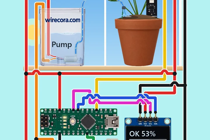 Same Arduino + pumpSelf-watering plant with a soil sensorWhen the soil dries out, the screen reads DRY, a small pump in the water reservoir starts and water runs through a clear hose into the pot.
 Next step: adds a servoPorch jack-in-the-box with an Arduino Nano, an HC-SR04, an MG995 servo and a TT gear motorHold your trick-or-treat pail out to the box.
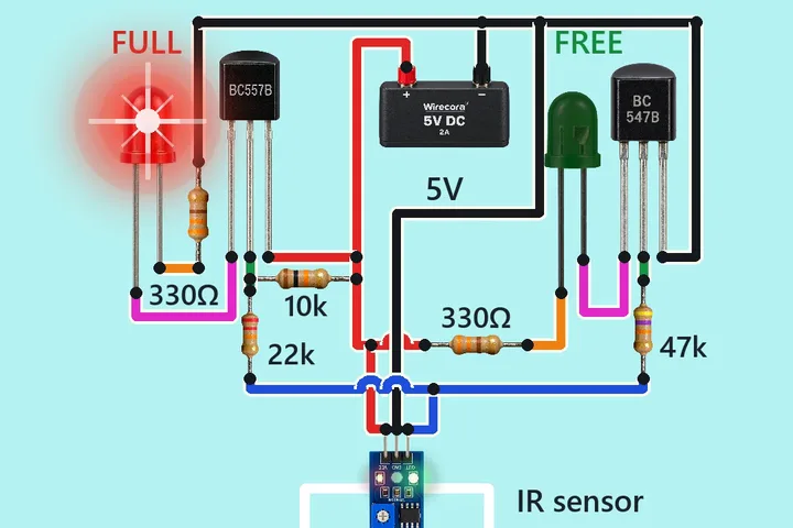 Something new: an IR sensorSmart parking system with two LEDsDrive the toy car into the bay and the red FULL LED lights while the green FREE LED goes dark.