Car horn relay wiring: a small button sounds two loud horns
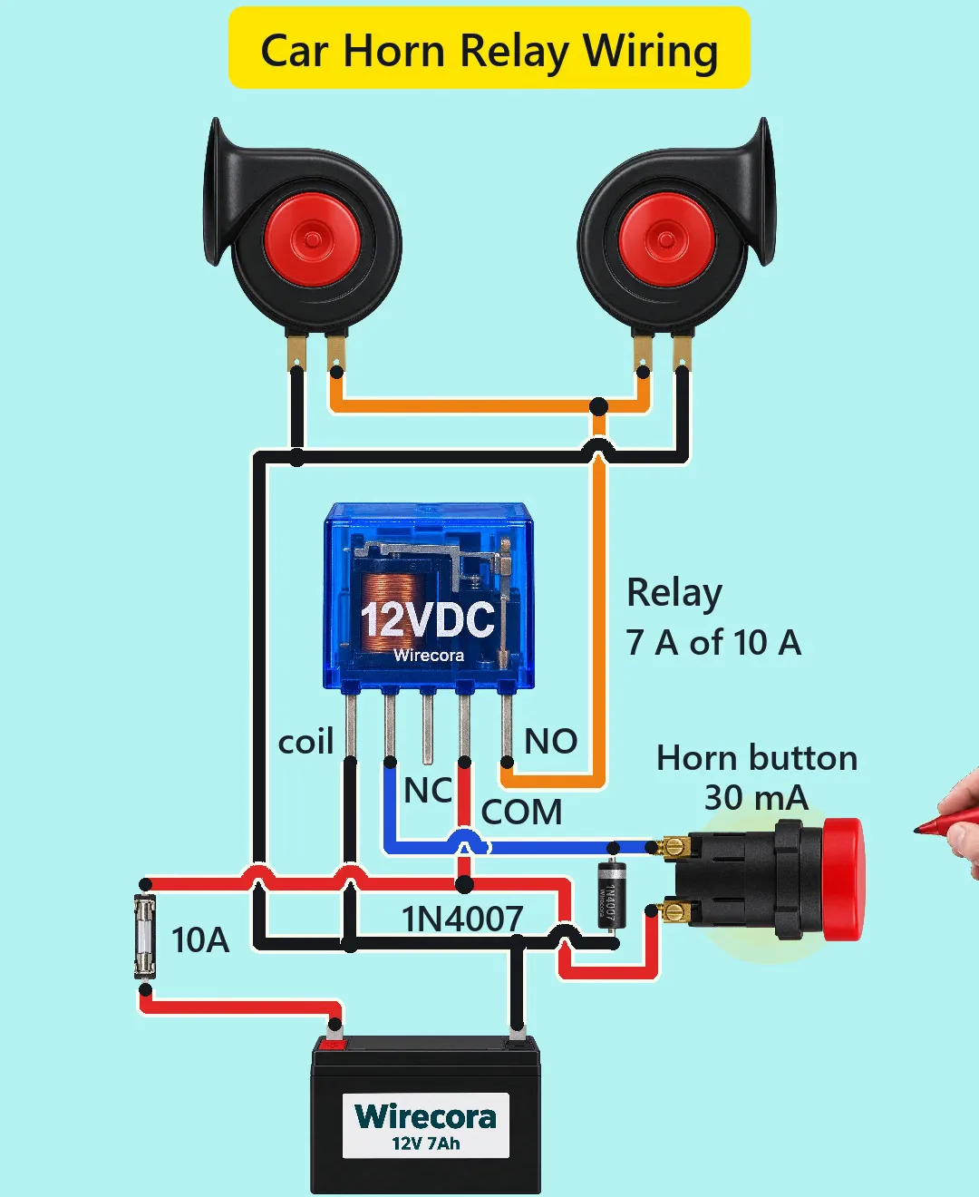
Press the horn button and a 12 V relay clicks in, so both horns sound. The button carries only the relay coil's current, about 30 mA. The relay contact carries the horns' current, about 7 A.
- 6 parts
- 6 wiring steps
- No code needed
- 12 V supply
Quick answer
The short version. Every pin is in the full wiring below.What you need
- 12 V battery
- 10 A fuse in a 5 x 20 mm holder
- 12 V relay
- Two 12 V car horns, about 3.5 A each
- 1N4007 diode
- Momentary push button, normally open
How to wire it
- Battery plus to one end of the fuse.
- Fuse other end to the relay's COM pin and to one button terminal.
- Other button terminal to relay coil pin A and to the 1N4007's band.
- Relay coil pin B, the 1N4007's other end, each horn's second terminal and battery minus together.
- Relay NO to the first terminal of both horns.
- The drawing has five crossings, each shown as a hop.
Before you power it: A car battery can deliver hundreds of amps, so every wire from the battery plus goes through a fuse placed close to the battery. Use wire and a relay rated for the horn current. Do not work on a car's wiring with the battery connected.
Parts list
- 12 V battery (the Short draws a small 12 V 7 Ah sealed lead-acid battery in place of a car battery)
- 10 A fuse in a 5 x 20 mm holder (the holder is rated 10 A)
- 12 V relay, coil about 400 ohm, contact 10 A at 30 V DC, pins from the left: coil, coil, NC, COM, NO
- Two 12 V car horns, about 3.5 A each (assumed, a typical value)
- 1N4007 diode (the band is the cathode)
- Momentary push button, normally open (30 mA through it; its 3 A rating is assumed)
Wiring, step by step
- Battery plus to one end of the fuse.
- Fuse other end to the relay's COM pin and to one button terminal. Every wire from the battery is fused, the button feed included.
- Other button terminal to relay coil pin A and to the 1N4007's band.
- Relay coil pin B, the 1N4007's other end, each horn's second terminal and battery minus together.
- Relay NO to the first terminal of both horns. A horn has no polarity here. NC stays unused.
- The drawing has five crossings, each shown as a hop. Where a wire hops over another, they do not touch.
How it works
- Pressing the button puts 12 V across the relay coil: 12 V / 400 ohm is about 30 mA. The relay pulls in about 10 ms later.
- The closed COM to NO contact feeds the horns from the fused battery plus. Two horns of about 3.5 A each draw about 7 A: 7 A of the relay's 10 A and of the 10 A fuse.
- When you let go, the button opens and the coil current dies away through the 1N4007, which takes the coil's voltage kick so it does not hurt the button.
- The thin button wire never carries the big horn current. That is the point of a relay.
- Many cars switch the horn relay's coil to ground at the steering wheel. A button on the plus side, as drawn, works the same way.
What the video simplifies
- The ignition switch of the viral original is left out. In a car the horn feed usually comes from a fused permanent supply anyway.
- A small 12 V 7 Ah battery stands in for the car battery (7 A for 0.3 s is about 0.6 mAh per honk).
- The relay is drawn with its five pins in one row. A real SRD-12VDC-SL-C type has staggered pins and its moving blade is COM, so check your relay's pin diagram. In a real car use a 30 A automotive relay and the fuse your horns need.
- Horn current of 3.5 A each and the button's rating are assumed values.
- The sound arcs, the glow, the small horn shake and the short fade after you let go are illustrations. A real horn stops within a few milliseconds.
- Current dots run slower than real. The parts are not drawn to scale.
- Fixed from the viral original (MW Electronics Lab): a flyback diode across the coil, a 10 A fuse in place of the 20 A one to match the relay contact and holder, and the button fed from the fused side.
- This circuit was checked by simulation and datasheets, not built.
You found this by searching. Here's the whole path.
- Read how it works
- See it work
- Build it
- Show it
Thirty seconds of video shows the circuit doing its job.
A car battery can deliver hundreds of amps, so every wire from the battery plus goes through a fuse placed close to the battery. Use wire and a relay rated for the horn current. Do not work on a car's wiring with the battery connected.
Built it, or stuck halfway? Post a photo in the Wirecora Discord. Questions get an answer every day.
What to build next
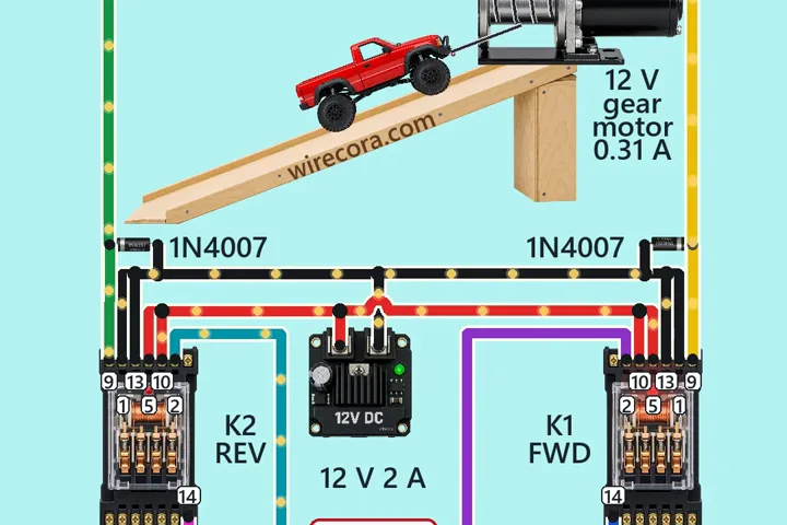 Same relayWinch with an interlockHold FORWARD and the winch pulls the car up the ramp.
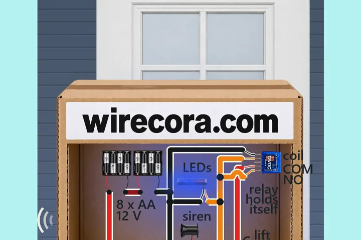 Next step: adds a buzzerParcel alarm that keeps goingLift the parcel and a siren sounds with red and blue strobe flashes.
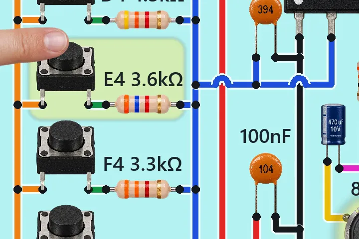 Something new: a 555 timerSix-key electronic piano with one NE555 timerPress a key and the speaker sings a note.