Six-key electronic piano with one NE555 timer
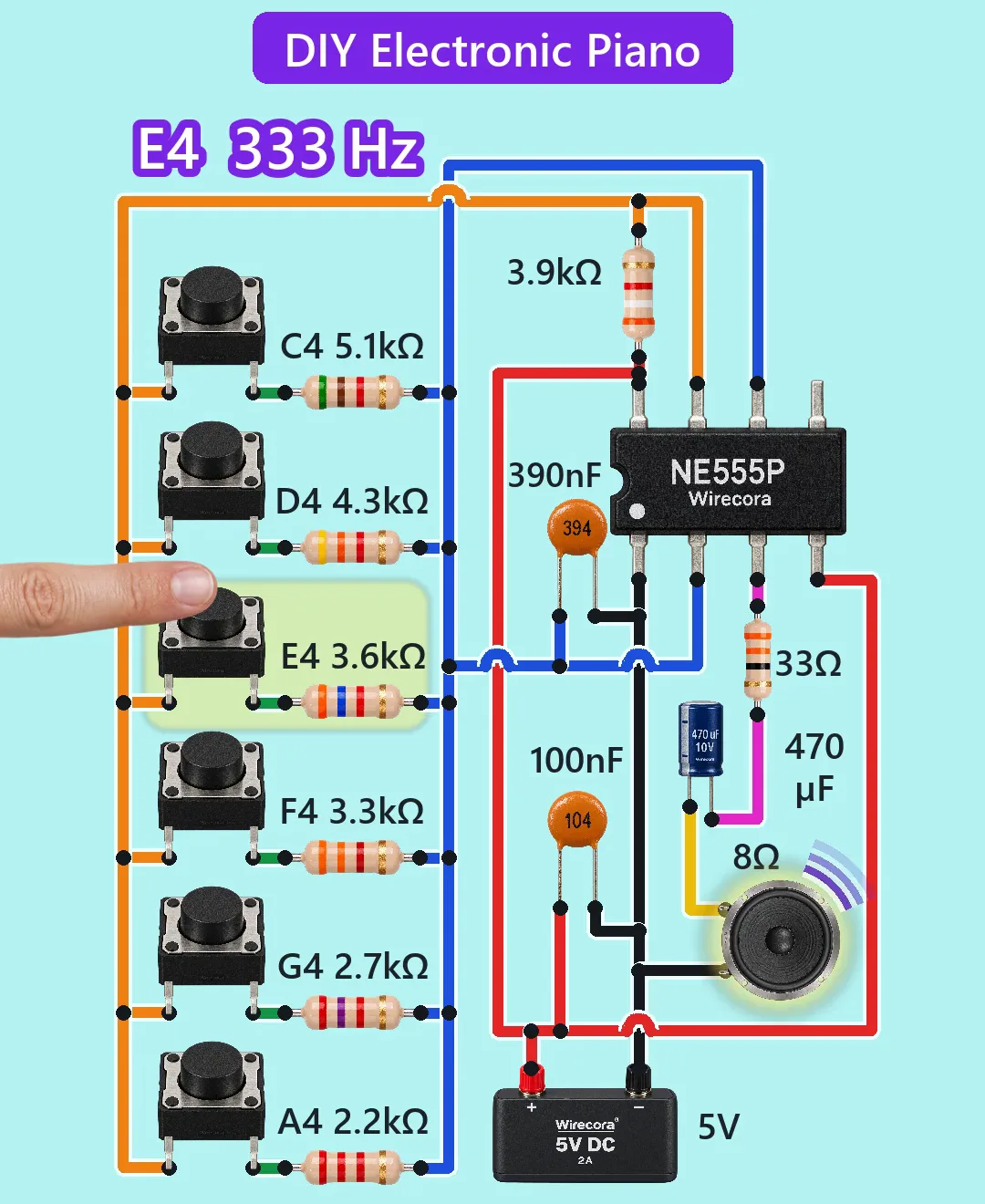
Press a key and the speaker sings a note. Each of the six push buttons connects its own resistor into the timing network of an NE555 timer, so every key sets a different pitch: C4 262 Hz, D4 296 Hz, E4 333 Hz, F4 352 Hz, G4 398 Hz, A4 446 Hz. With no key pressed the speaker is silent.
- 10 parts
- 6 wiring steps
- No code needed
- 5 V supply
Quick answer
The short version. Every pin is in the full wiring below.What you need
- NE555 timer
- 6 push buttons
- Six key resistors, 5 % 1/4 W: 5.1 k
- 3.9 k resistor, 5 %, between plus and pin 7
- 390 nF capacitor, film or ceramic, 16 V or more
- 100 nF ceramic capacitor
- 33 ohm resistor
- 470 uF 10 V electrolytic capacitor
- Small 8 ohm speaker
- 5 V DC supply, regulated, 2 A module
How to wire it
- Supply plus (red) to NE555 pin 8 (VCC) and pin 4 (RESET), to the top of the 3.9 k resistor, and to one end of the 100 nF capacitor.
- Supply minus (black) to pin 1 (GND), to the other end of the 100 nF capacitor, to the minus end of the 390 nF capacitor, and to the speaker's second lug.
- The other end of the 3.9 k resistor to pin 7 (DISCH).
- Each button's right leg goes to its own resistor (5.1 k, 4.3 k, 3.6 k, 3.3 k, 2.7 k or 2.2 k, top to bottom).
- Pin 3 (OUT) to the 33 ohm resistor, then to the plus (long leg, no stripe) of the 470 uF capacitor.
- Pin 5 (CONT) stays open.
Before you power it: Everything here runs on 5 V DC from a regulated supply. Press one key at a time: two keys together put two resistors in parallel and raise the pitch.
Parts list
- NE555 timer (for example TI NE555P, DIP-8), 5 V supply
- 6 push buttons, 6 x 6 mm tactile type, normally open
- Six key resistors, 5 % 1/4 W: 5.1 k (C4), 4.3 k (D4), 3.6 k (E4), 3.3 k (F4), 2.7 k (G4), 2.2 k (A4)
- 3.9 k resistor, 5 %, between plus and pin 7
- 390 nF capacitor, film or ceramic, 16 V or more (marked 394), the timing capacitor
- 100 nF ceramic capacitor (marked 104) across the supply at the chip
- 33 ohm resistor, 5 %, 1/4 W, in series with the speaker
- 470 uF 10 V electrolytic capacitor (the stripe is the minus side)
- Small 8 ohm speaker
- 5 V DC supply, regulated, 2 A module
Wiring, step by step
- Supply plus (red) to NE555 pin 8 (VCC) and pin 4 (RESET), to the top of the 3.9 k resistor, and to one end of the 100 nF capacitor.
- Supply minus (black) to pin 1 (GND), to the other end of the 100 nF capacitor, to the minus end of the 390 nF capacitor, and to the speaker's second lug.
- The other end of the 3.9 k resistor to pin 7 (DISCH). Pin 7 also goes to the left leg of every one of the six buttons.
- Each button's right leg goes to its own resistor (5.1 k, 4.3 k, 3.6 k, 3.3 k, 2.7 k or 2.2 k, top to bottom). The far end of all six key resistors joins one line, and that line goes to pins 6 and 2 (THRES and TRIG, tied together) and to the plus end of the 390 nF capacitor.
- Pin 3 (OUT) to the 33 ohm resistor, then to the plus (long leg, no stripe) of the 470 uF capacitor. The capacitor's minus (stripe) goes to the speaker's first lug.
- Pin 5 (CONT) stays open. Where two wires hop over each other in the picture they do not touch.
How it works
- The NE555 is wired as an astable oscillator. The 390 nF capacitor charges through the 3.9 k and the chosen key resistor, and discharges through the key resistor into pin 7. Each time it reaches 2/3 of the supply the output flips low, and at 1/3 it flips high again.
- Each button sits in series with its own resistor, so a pressed key puts exactly one key resistor between pin 7 and the capacitor. With no key pressed there is no discharge path and the chip cannot oscillate.
- The frequency is f = 1 / (ln2 x (3.9 k + 2 x R_key) x 390 nF). A smaller key resistor gives a higher note, so the keys further down the column play higher. The six notes land within 1.5 % of the equal-tempered C4 to A4 on paper, and within 1 % in a simulation of this circuit.
- Frequency and duty cycle do not depend on the supply voltage, because the thresholds are fixed fractions of it.
- The 33 ohm resistor and the 470 uF capacitor keep the NE555 output current at about 85 mA at start-up (the datasheet limit is 200 mA). Without the 33 ohm resistor the start-up surge would be about 370 mA. The capacitor also blocks DC, so no steady current flows through the speaker.
- The speaker gets about 10 mW, so it is quiet. An LM386 amplifier is the usual next step.
What the video simplifies
- The hand, the yellow highlight on the pressed key's row, the sound arcs and the speaker cone movement are graphics. The cone is drawn pulsing at about 9 times a second; the real cone moves at the note frequency.
- The readout shows the circuit's computed frequency. For example E4 shows 333 Hz; the equal-tempered E4 is 329.6 Hz.
- The sound in the video is synthesised at the circuit's frequencies.
- The speaker is drawn larger than a 10 mW toy speaker would be.
- With 5 % resistors and a 10 % capacitor the notes can be off by several percent. Use 1 % resistors and a 5 % capacitor, or trim, for an in-tune piano. An error in the timing capacitor moves all six notes together.
- Pin 5 is left open; if a real build is noisy, add 10 nF from pin 5 to ground.
- Nothing was built for this video: the values were calculated, checked against the TI NE555 datasheet and simulated.
You found this by searching. Here's the whole path.
- Read how it works
- See it work
- Build it
- Show it
Thirty seconds of video shows the circuit doing its job.
Everything here runs on 5 V DC from a regulated supply. Press one key at a time: two keys together put two resistors in parallel and raise the pitch.
Built it, or stuck halfway? Post a photo in the Wirecora Discord. Questions get an answer every day.
What to build next
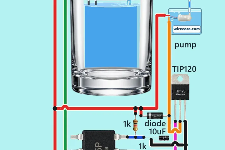 Same 555 timerGlass that fills itself and stops near the topPress START once and a small pump fills the glass.
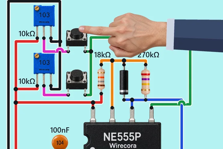 Next step: adds a servoServo control with a 555 and two buttonsHold the top button and the servo horn swings one way.
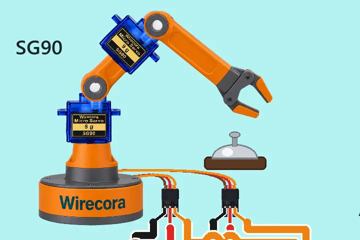 Something new: an ArduinoRobotic arm with an Arduino Nano, two SG90 servos and two slide potsSlide one knob and the shoulder servo turns, slide the other and the elbow servo turns.