Light sensor that plays the dino game
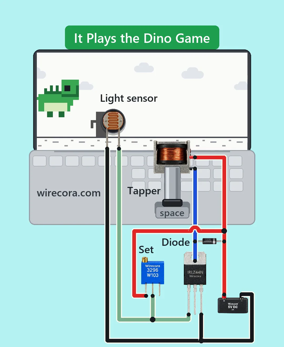
A light sensor stuck on a laptop screen watches for a dark cactus sliding toward the dinosaur. When the cactus covers the sensor, a plunger taps the space bar and the dinosaur jumps. No Arduino and no code run here: one transistor does it all.
- 7 parts
- 5 wiring steps
- No code needed
- 5 V supply
Quick answer
The short version. Every pin is in the full wiring below.What you need
- IRLZ44N logic-level N-channel MOSFET, TO-220
- GL5528 light-dependent resistor in a short black tube
- 10 kohm multi-turn trimmer, called Set
- 1N4007 diode across the solenoid coil
- 5 V push-pull solenoid
- 5 V 2 A power supply
- A laptop showing the offline dinosaur game
How to wire it
- Supply plus (+5 V) to the solenoid's red lead, the diode's band (cathode) and trimmer pin P1.
- Supply minus to the IRLZ44N source and to one lead of the light sensor.
- Trimmer wiper to the IRLZ44N gate and to the other lead of the light sensor.
- Solenoid black lead to the IRLZ44N drain and to the diode's plain end (anode).
- Trimmer pin P3 stays open.
Before you power it: Everything runs on 5 V, about 1.1 A while the plunger is out. If the screen goes dark the coil stays on and gets hot, so unplug it when you stop.
Parts list
- IRLZ44N logic-level N-channel MOSFET, TO-220 (from the front the legs are gate, drain, source; the metal tab is the drain)
- GL5528 light-dependent resistor in a short black tube (its two leads have no polarity)
- 10 kohm multi-turn trimmer, called Set (the 3296W type, about 25 turns end to end; clockwise raises the resistance between pin P1 and the wiper)
- 1N4007 diode across the solenoid coil (band to plus)
- 5 V push-pull solenoid, 1.1 A, 3 mm stroke, about 80 g (the Adafruit 2776 type), on a rigid bracket above the space bar
- 5 V 2 A power supply
- A laptop showing the offline dinosaur game (not an electronic part)
Wiring, step by step
- Supply plus (+5 V) to the solenoid's red lead, the diode's band (cathode) and trimmer pin P1.
- Supply minus to the IRLZ44N source and to one lead of the light sensor.
- Trimmer wiper to the IRLZ44N gate and to the other lead of the light sensor. The trimmer and the sensor make a voltage divider, and the gate reads its middle.
- Solenoid black lead to the IRLZ44N drain and to the diode's plain end (anode). The drain is the metal tab, so the wire goes on the tab and the middle leg stays empty.
- Trimmer pin P3 stays open. The trimmer is used as a variable resistor: one end and the wiper.
How it works
- On a white screen the sensor's resistance is low (about 1.2 kohm, an estimate), so the gate sits low, about 1.2 V with Set at 3.8 kohm (the setting for a transistor that switches on at about 1.5 V), and the IRLZ44N stays off. A transistor that switches on nearer 1 V needs Set turned further.
- A dark cactus slides under the sensor and its resistance rises (about 5.2 kohm). The gate goes to about 2.9 V, above the IRLZ44N's 1 to 2 V threshold, and the transistor switches on.
- About 1.1 A flows through the 5 V solenoid coil, the plunger snaps out and taps the space bar, and the dinosaur jumps. The coil is on for about 0.2 to 0.3 s of every 2 s, which is about 10 % of the time.
- When the cactus has passed, the gate falls, the transistor turns off and the plunger returns. The diode catches the coil's voltage kick: the drain peaks at about 5.9 V with it, and the simulation clamps at 55.8 V without it.
- To set it up, turn Set clockwise until the solenoid stops on a white screen, then about one more turn, no more, until the IRLZ44N stays cold. The sensor sits 30 to 40 mm ahead of the dinosaur at normal zoom, worked out from the game's code, not tried.
What the video simplifies
- It does lose. By calculation a run ends within about a minute at best; nobody has tried it. Birds arrive at about 40 s and are not handled. At about 700 points the game turns itself to night, the sensor reads dark and the plunger stays down, and you cannot switch that off. A fixed sensor also falls behind as the game speeds up. The clip stays at the game's starting speed.
- The screen light levels, 80 g being enough for your key (laptop keys vary), and the coil inductance are assumed, not measured. Every screen and sensor tube needs its own Set setting.
- All the cacti are drawn wider than the real game's. A real small cactus never fully covers the sensor, so it can be missed if Set is turned too far.
- The plunger travel is drawn larger than the real 3 mm, and its stroke and return are drawn slower. The jumps are slower than the real game's (0.8 s and 1.0 s against 0.62 s at the start).
- The sensor is drawn facing you; a real one faces the screen inside its tube. No mount is drawn, the parts are drawn large and shown beside the laptop for the picture.
- The gate wire turns bright green only to show the gate is high, and the coil's glow is only a marker.
- The game on screen is our own drawing, not made by or connected with Google. The simulation's MOSFET turn-on is simplified, so rely on the gate voltages.
- This circuit was checked by simulation and against the datasheets, not built.
You found this by searching. Here's the whole path.
- Read how it works
- See it work
- Build it
- Show it
Next: see it work
Thirty seconds of video shows the circuit doing its job.
Then build it
Everything runs on 5 V, about 1.1 A while the plunger is out. If the screen goes dark the coil stays on and gets hot, so unplug it when you stop.
Then show it
Built it, or stuck halfway? Post a photo in the Wirecora Discord. Questions get an answer every day.
What to build next
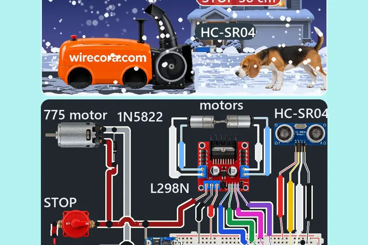 Same MOSFETRobot snow blower that stops for a dogA small robot snow blower clears a driveway, stops dead when a dog runs into its lane, and drives on once the dog is gone.
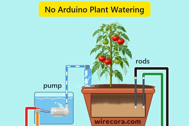 Next step: adds a pumpSelf-watering plant with one MOSFET (no Arduino)Two steel rods in the soil decide when the pump runs.
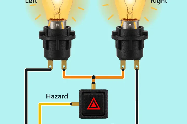 Something new: a lampCar hazard lights with a thermal flasherTwo amber car bulbs blink on their own with the familiar click-clack.