Hand-crank motor generator
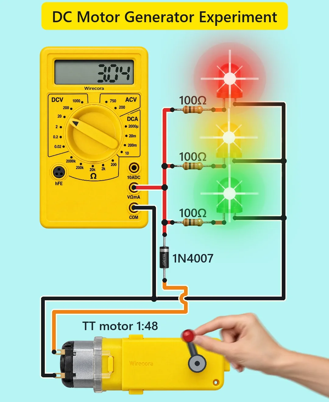
A hand turns a crank on a small TT gear motor. The motor works as a generator and makes about 3.7 V. A diode and three 100 ohm resistors feed three LEDs (red, yellow, green), and a meter on the rail reads about 3 V.
- 5 parts
- 4 wiring steps
- No code needed
Quick answer
The short version. Every pin is in the full wiring below.What you need
- TT gear motor
- 1N4007 diode
- 3 x 100 ohm resistor
- 3 x 5 mm LED: red, yellow, green
- Multimeter on DC V 20
How to wire it
- Motor terminal A goes to the anode of the 1N4007.
- From the diode's cathode runs the + rail.
- The three LED cathodes go back to motor terminal B.
- The meter's red lead (VΩmA socket) goes to the + rail.
Before you power it: Low voltage only, about 3 to 4 V. Do not crank hard against the gearbox. Keep fingers away from the crank handle.
Parts list
- TT gear motor, 3 to 6 V, 1:48 gearbox, with a crank on the output shaft
- 1N4007 diode
- 3 x 100 ohm resistor (brown, black, brown, gold)
- 3 x 5 mm LED: red, yellow, green
- Multimeter on DC V 20 (the 20 V range)
Wiring, step by step
- Motor terminal A goes to the anode of the 1N4007. The band (cathode) faces the LEDs.
- From the diode's cathode runs the + rail. It feeds three branches, each a 100 ohm resistor and one LED, with the LED's long lead (anode) toward the resistor.
- The three LED cathodes go back to motor terminal B.
- The meter's red lead (VΩmA socket) goes to the + rail. The black lead (COM) goes to the ground side, motor terminal B.
How it works
- Turning a motor makes a voltage. The 1:48 gearbox speeds the motor up: at about 2.3 turns per second at the crank (about 6,650 rpm at the motor inside) it makes about 3.7 V.
- This motor makes about 27 mV for every turn per minute at its output shaft (from the maker's rating).
- After the motor's own resistance and the 0.7 V drop of the diode, about 2.9 V is left on the rail.
- Each LED takes about 1.9 to 2.0 V and each resistor about 0.9 to 1.0 V. So each LED gets about 9 to 10 mA, and about 29 mA flows in total.
- The meter reads 2.8 to 3.0 V while you crank. A bare small motor turned by hand without a gearbox gives under 0.1 V.
- The single diode passes current one way only. The motor has no polarity marks, so which crank direction lights the LEDs is just a matter of how you wired it. Crank the other way and nothing lights.
What the video simplifies
- A fingertip pinch turning a stiff 1:48 gearbox this fast is dramatised. A real hand needs a firm grip.
- The hand's speed changes about 5 percent within each turn, and the crank and hand have motion blur.
- The motor constant comes from the Adafruit TT motor data. Real motors vary by about 10 percent, so each LED would get between about 7 and 19 mA, all inside its rating.
- The motor's inner resistance of 4 ohm is assumed.
- The LED glow is drawn as halos. The meter reading comes from the model, and the meter updates 2 to 3 times a second, so it lags the crank.
- Changed from the viral original: a plain TT gear motor on its own two terminals (not a modified servo), a diode, one resistor per LED, and a meter reading of about 3 V (the original showed 6 V).
- Checked by simulation and datasheets only. It was not built.
You found this by searching. Here's the whole path.
- Read how it works
- See it work
- Build it
- Show it
Next: see it work
Thirty seconds of video shows the circuit doing its job.
Then build it
Low voltage only, about 3 to 4 V. Do not crank hard against the gearbox. Keep fingers away from the crank handle.
Then show it
Built it, or stuck halfway? Post a photo in the Wirecora Discord. Questions get an answer every day.
What to build next
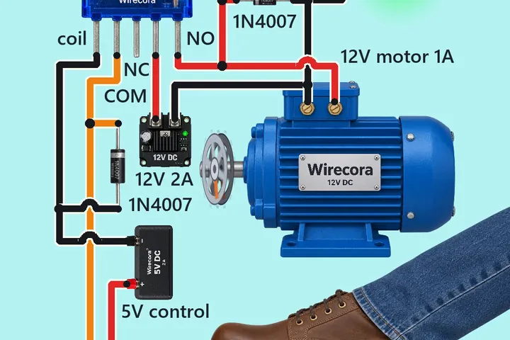 Same motorFoot pedal motor switch with a 5 V relay and a 12 V motorStep on the pedal and the 12 V motor runs and the green RUN lamp lights.
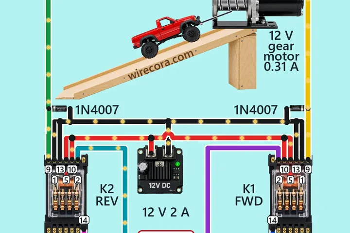 Next step: adds a relayWinch with an interlockHold FORWARD and the winch pulls the car up the ramp.
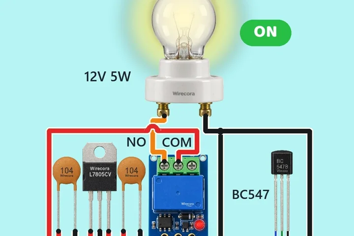 Something new: a relayTouch switch lampA finger taps a red TTP223 touch pad.