Fan that turns on by itself when it gets hot (NTC thermistor and IRFZ44N MOSFET)
A hair dryer warms a 10k NTC thermistor. When the thermistor gets hot enough, an IRFZ44N MOSFET switches the fan on; when the thermistor cools down again, the fan stops. It is an on/off switch at about 43 C for a typical part, not a speed control.
- 7 parts
- 5 wiring steps
- No code needed
- 12 V supply
Quick answer
The short version. Every pin is in the full wiring below.What you need
- 12 V 80 mm brushless fan, about 75 mA
- 10k NTC thermistor
- 1.5k resistor
- IRFZ44N N-channel MOSFET
- 1N4007 diode
- 12 V battery or 12 V supply
- A 1 A fuse in the plus wire at the battery
How to wire it
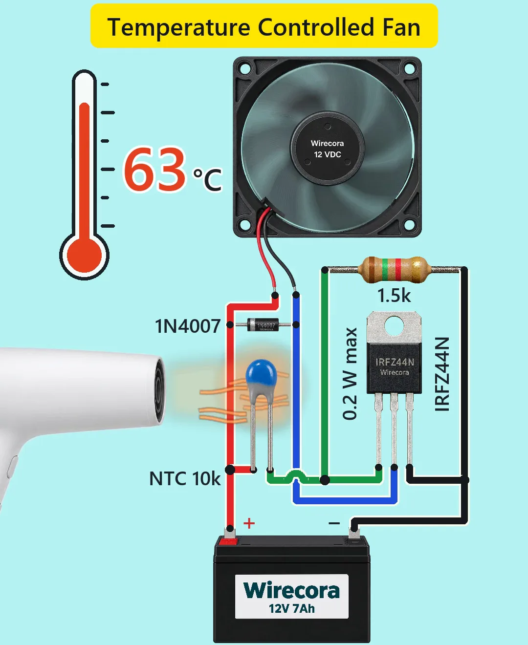
- Battery plus (red) to the thermistor's first lead, the fan's red lead and the band end of the 1N4007.
- Thermistor's second lead to the 1.5k resistor and to the MOSFET gate (the green net).
- MOSFET drain to the fan's black lead and to the other end of the 1N4007 (the blue net).
- Battery minus (black) to the other end of the 1.5k resistor and to the MOSFET source.
- In the drawing the green gate wire crosses the blue drain wire once, on a hop.
Before you power it: Everything runs on 12 V. Warm the thermistor with warm air only, never a flame, and keep the bead under its 125 C limit. Put a 1 A fuse in the plus wire at the battery, and do not empty a lead-acid battery completely.
Parts list
- 12 V 80 mm brushless fan, about 75 mA (red lead plus, black lead minus; it runs from 4.5 to 13.8 V)
- 10k NTC thermistor (B25/85 about 3977 K, 500 mW, -40 to 125 C; it has no polarity)
- 1.5k resistor (brown, green, red, gold)
- IRFZ44N N-channel MOSFET (front view, legs from the left: gate, drain, source; 55 V, threshold 2 to 4 V, gate limit 20 V)
- 1N4007 diode (the band is the cathode)
- 12 V battery or 12 V supply (the Short draws a 12 V 7 Ah sealed lead-acid battery)
- A 1 A fuse in the plus wire at the battery (not drawn in the Short)
Wiring, step by step
- Battery plus (red) to the thermistor's first lead, the fan's red lead and the band end of the 1N4007.
- Thermistor's second lead to the 1.5k resistor and to the MOSFET gate (the green net).
- MOSFET drain to the fan's black lead and to the other end of the 1N4007 (the blue net). The diode sits across the fan with its band on the plus side.
- Battery minus (black) to the other end of the 1.5k resistor and to the MOSFET source.
- In the drawing the green gate wire crosses the blue drain wire once, on a hop. Where a wire hops over another, they do not touch.
How it works
- The thermistor and the 1.5k resistor form a voltage divider between plus 12 V and minus. The gate voltage is 12 V x 1.5k / (R_NTC + 1.5k).
- A hot thermistor has a low resistance, so the gate voltage rises: about 1.6 V at 25 C, 2.7 V at 40 C, 3.6 V at 50 C and 4.5 V at 60 C.
- Once the gate passes the MOSFET's threshold (typically 3 V) the MOSFET connects the fan's minus wire to battery minus and the fan runs on the full 12 V. A power MOSFET has so much gain that the fan goes from off to full within about 1 C. It does not follow the temperature smoothly; what looks like a speed-up in the Short is the fan's own inertia.
- The switch-on temperature depends on the part: from about 30 C (a 2 V threshold) to about 54 C (a 4 V threshold), 43 C for a typical 3 V one. Set it with the resistor: a larger one switches cooler, a smaller one hotter (1k is about 10 C hotter). A 5k trimmer makes it adjustable.
- The 1N4007 across the fan catches the voltage kick when the fan switches off, and protects the MOSFET.
- There is no hysteresis. Right at the switching temperature the fan can hover half on; the MOSFET then dissipates at most about 0.2 W (the 0.2 W max on screen), so no heat sink is needed.
- The IRFZ44N is not a logic-level part, but for 75 mA it is fully on at about 5 V on the gate.
What the video simplifies
- Heating and cooling are sped up about 10 times. A real thermistor bead takes several seconds in moving air and about 15 seconds in still air.
- The thermometer and the number are added for the animation; they show the thermistor temperature. There is no display in the circuit.
- The fan is drawn turning slowly (a real 80 mm fan at 2600 rpm is a blur), and its hub label is kept still so it can be read.
- The dryer air of about 70 C at the sensor and the fan's run-up time are assumed values.
- The parts are drawn larger than the battery and the dryer.
- Fixed from the viral original: a hair dryer instead of an open flame, a 1N4007 across the fan, and 1.5k instead of 1k.
- This circuit was checked by simulation and datasheets, not built.
You found this by searching. Here's the whole path.
- Read how it works
- See it work
- Build it
- Show it
Thirty seconds of video shows the circuit doing its job.
Everything runs on 12 V. Warm the thermistor with warm air only, never a flame, and keep the bead under its 125 C limit. Put a 1 A fuse in the plus wire at the battery, and do not empty a lead-acid battery completely.
Built it, or stuck halfway? Post a photo in the Wirecora Discord. Questions get an answer every day.
What to build next
 Same MOSFETRobot snow blower that stops for a dogA small robot snow blower clears a driveway, stops dead when a dog runs into its lane, and drives on once the dog is gone.
 Next step: adds a pumpSelf-watering plant with one MOSFET (no Arduino)Two steel rods in the soil decide when the pump runs.
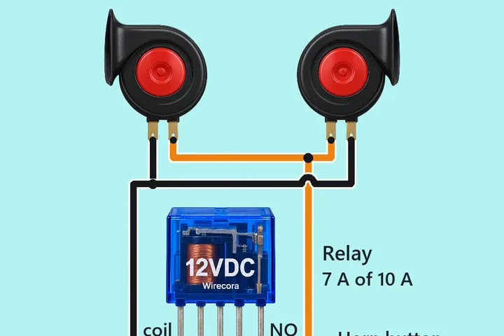 Something new: a relayCar horn relay wiring: a small button sounds two loud hornsPress the horn button and a 12 V relay clicks in, so both horns sound.