12 V ZVS induction heater
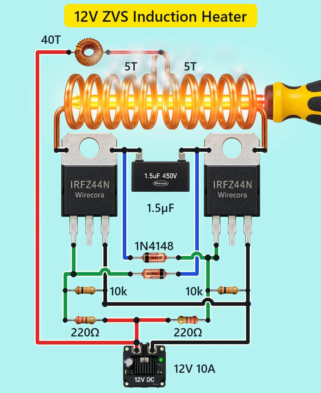
A 12 V supply drives a coil with two MOSFETs and a capacitor. The coil and the capacitor ring together at about 150 kHz. The changing field heats a steel rod inside the coil until it glows. This is a ZVS (Mazzilli) driver.
- 9 parts
- 6 wiring steps
- No code needed
- 12 V supply
Quick answer
The short version. Every pin is in the full wiring below.What you need
- 12 V DC supply rated well above 10 A
- Choke, 100 uH
- Work coil, 5 + 5 turns, centre tapped
- Two IRFZ44N MOSFETs
- 1.5 uF film capacitor across the coil ends
- Two 220 ohm resistors, 1/2 W
- Two 10 kohm resistors
- Two 1N4148 diodes
- A heatsink for the MOSFETs
How to wire it
- +12 V to the choke.
- The two coil ends go to the drains (tabs) of the two MOSFETs.
- On each MOSFET, the gate goes through a 220 ohm resistor to +12 V and through a 10 kohm resistor to ground.
- A 1N4148 runs from each gate to the other MOSFET's drain, with its band toward the drain.
- Both sources go to 12 V minus.
- Both tabs are drains.
Before you power it: DANGER. The coil and the steel get very hot and cause burns. Do not touch them while it runs or just after. Keep flammable things away. At 12 V the supply can still push 10 A and more through thin wire, and the tank current is about 50 A, so use thick wire, a fuse and good joints. Do not use a motor-run capacitor. The fast field can heat rings and watches and can disturb pacemakers, so keep them away. Never work on it while it is on.
Parts list
- 12 V DC supply rated well above 10 A (a small work piece draws about 8.5 A, a bigger one 12 A and more)
- Choke, 100 uH (illustrative), able to carry about 10 A without saturating
- Work coil, 5 + 5 turns, centre tapped (about 0.75 uH end to end, illustrative; real coils are usually copper tube)
- Two IRFZ44N MOSFETs (pins G, D, S; the metal tab is the drain)
- 1.5 uF film capacitor across the coil ends (pulse-rated MKP film; the tank current is about 50 A)
- Two 220 ohm resistors, 1/2 W
- Two 10 kohm resistors
- Two 1N4148 diodes
- A heatsink for the MOSFETs (not drawn)
Wiring, step by step
- +12 V to the choke. The other end of the choke goes to the centre tap of the work coil.
- The two coil ends go to the drains (tabs) of the two MOSFETs. The 1.5 uF capacitor sits across the coil ends.
- On each MOSFET, the gate goes through a 220 ohm resistor to +12 V and through a 10 kohm resistor to ground.
- A 1N4148 runs from each gate to the other MOSFET's drain, with its band toward the drain.
- Both sources go to 12 V minus.
- Both tabs are drains. Use separate heatsinks, or insulate the tabs from a shared one.
How it works
- The two MOSFETs take turns. One turns on while the other turns off. Each gate is held up by its 220 ohm resistor and pulled down through the other MOSFET's drain by its diode.
- The coil and the capacitor form a resonant tank. In a simulation it rings at about 150 kHz with an empty coil and about 143 kHz with steel inside.
- The MOSFETs switch when the drain voltage is near zero. That is why this driver runs cool for its power. In a simulation the drains reach about 37 V and the gates sit near 11.7 V.
- The choke keeps the supply current steady while the tank swings.
- The fast field makes eddy currents in the steel. The currents heat it. A small work piece draws about 8.5 A in the simulation.
What the video simplifies
- Heating is sped up many times. A real 12 V build takes minutes to bring this much steel to red heat.
- The glow and the smoke are drawn. Real smoke is oil or paint burning off the steel. The oscillation itself is silent; the sound is added.
- One 1.5 uF block stands for the capacitor bank. Coil (0.75 uH) and choke (100 uH) values are illustrative. The heatsinks are not drawn.
- The 150 kHz, 143 kHz and 37 V figures come from a simulation (ngspice) of those assumed values. They are not measurements. The 8.5 A figure assumes a work piece modelled as 8 ohm. A bigger piece draws 12 A and more.
- Switch-on: with an empty coil and an instant switch-on the drains can spike to about 56 to 62 V for under a millisecond. That is past the IRFZ44N's 55 V rating, but the part is avalanche rated. Switch on with steel in the coil, or from a supply that ramps up, or use 100 V MOSFETs with the same pinout.
- This circuit was checked by simulation and datasheets only. It was not built.
You found this by searching. Here's the whole path.
- Read how it works
- See it work
- Build it
- Show it
Thirty seconds of video shows the circuit doing its job.
DANGER. The coil and the steel get very hot and cause burns. Do not touch them while it runs or just after. Keep flammable things away. At 12 V the supply can still push 10 A and more through thin wire, and the tank current is about 50 A, so use thick wire, a fuse and good joints. Do not use a motor-run capacitor. The fast field can heat rings and watches and can disturb pacemakers, so keep them away. Never work on it while it is on.
Built it, or stuck halfway? Post a photo in the Wirecora Discord. Questions get an answer every day.
What to build next
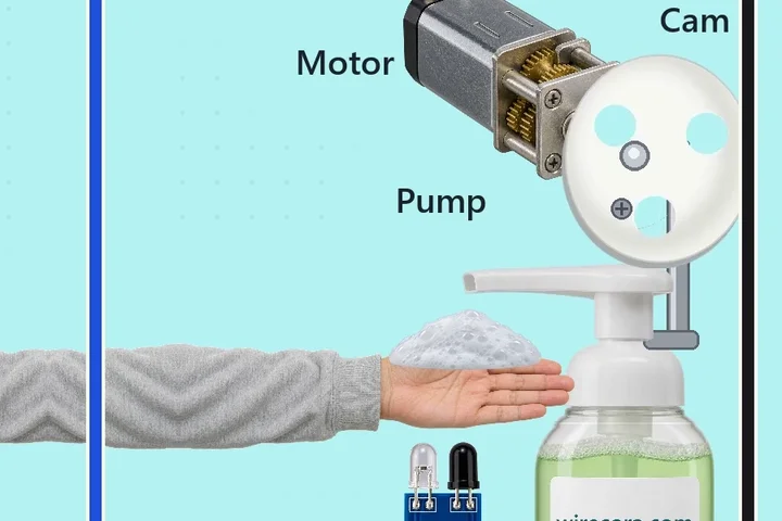 Same MOSFETTouchless foam soap dispenserYou hold a hand under the nozzle.
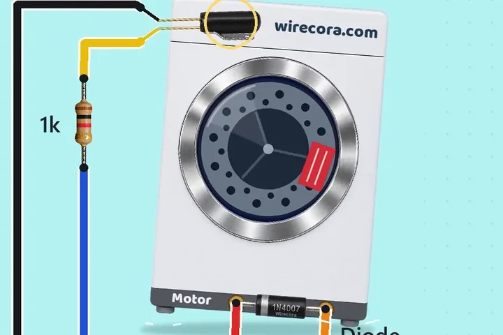 Next step: adds a motorWasher unbalanced-load stopA heavy load sticks to one side of the drum and the washer rocks harder and harder.
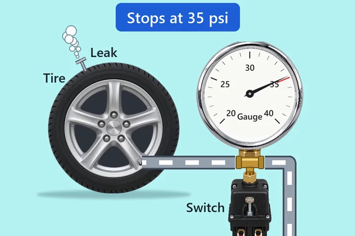 Something new: a relayTyre pump that stops itself at 35 psiA pressure switch on the tyre valve tells the pump when to stop and when to start again.