Washer unbalanced-load stop
A heavy load sticks to one side of the drum and the washer rocks harder and harder. At the biggest lean a ball switch on top closes and cuts the motor. The drum coasts down and the washer settles. About one and a half seconds after the last tick of the switch, the motor starts again by itself.
- 8 parts
- 6 wiring steps
- No code needed
- 12 V supply
Quick answer
The short version. Every pin is in the full wiring below.What you need
- 12 V 2 A adapter and a DC barrel jack
- SW-520D ball tilt switch
- IRFZ44N MOSFET
- 470k resistor
- 10 µF 25 V electrolytic capacitor
- 1k resistor
- 1N4007 diode
- 12 V DC brush motor
How to wire it
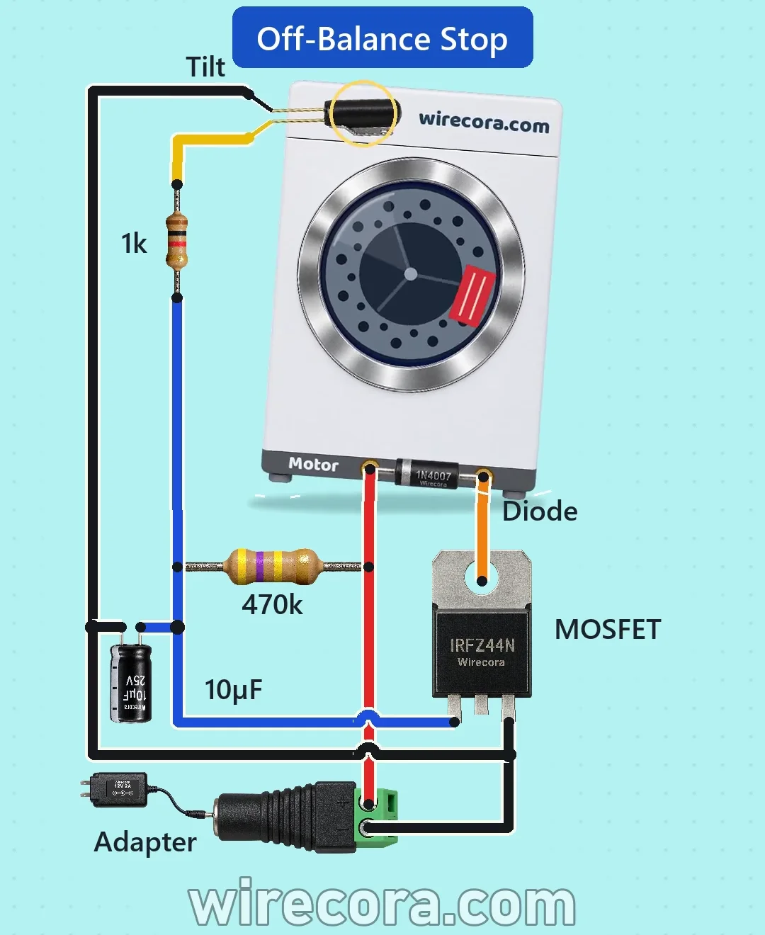
- Jack plus (+12 V) goes to the motor's plus terminal and to one end of the 470k resistor.
- The motor's minus terminal goes to the MOSFET drain (the tab).
- The other end of the 470k goes to the MOSFET gate, to the plus leg of the 10 µF capacitor and to one end of the 1k resistor.
- The other end of the 1k goes to one lead of the tilt switch.
- Jack minus (ground) goes to the MOSFET source and to the capacitor's minus leg.
- Mount the tilt switch flat on top of the washer with its pins tipped about 5 degrees down.
Before you power it: 12 V DC only. Never connect this to a real mains washing machine. With no fuse, the adapter is the only current limit, so keep the wires insulated.
Parts list
- 12 V 2 A adapter and a DC barrel jack
- SW-520D ball tilt switch
- IRFZ44N MOSFET
- 470k resistor
- 10 µF 25 V electrolytic capacitor
- 1k resistor
- 1N4007 diode
- 12 V DC brush motor (inside the washer)
Wiring, step by step
- Jack plus (+12 V) goes to the motor's plus terminal and to one end of the 470k resistor.
- The motor's minus terminal goes to the MOSFET drain (the tab). The 1N4007 sits across the two motor terminals, with its band on the plus side.
- The other end of the 470k goes to the MOSFET gate, to the plus leg of the 10 µF capacitor and to one end of the 1k resistor.
- The other end of the 1k goes to one lead of the tilt switch. The other lead of the tilt switch goes to ground.
- Jack minus (ground) goes to the MOSFET source and to the capacitor's minus leg.
- Mount the tilt switch flat on top of the washer with its pins tipped about 5 degrees down. The 5 degrees is our own choice, so set it by testing.
How it works
- While the washer is calm the tilt switch is open. The 470k charges the 10 µF capacitor (time constant 470k x 10 µF = 4.7 s). When the gate passes the MOSFET's threshold of 2 to 4 V the motor switches on, gently at first, and the drum spins.
- When the washer leans far enough toward the pin end, the ball inside the switch rolls onto the contacts and closes it. The capacitor then empties through the 1k in milliseconds. The gate drops to 0 V, the MOSFET switches off and the motor stops.
- The 1k also holds the current through the switch near 12 mA at 12 V.
- The drum coasts down and the rocking dies away. The ball rolls off the contacts, the switch opens and the 470k charges the capacitor again. About 1.35 s after the last tick the gate passes 3 V and the motor comes back on. The cycle repeats while the load stays unbalanced.
- The 1N4007 takes the voltage kick of the motor when it switches off.
What the video simplifies
- The rocking, the drum speed and the tilt switch (drawn about 7 times real size) are drawn bigger and slower so you can see them.
- The 5 degree bracket, the 1.2 s coast, the motor current (about 0.5 A with the drum) and the ball's contact time are our assumptions. The 20 to 30 mA switch rating comes from shop listings, because the maker gives none.
- The maker's sheet for the SW-520D is not clear about the angle at which a switch that leans toward its pins closes (it names about 10 degrees for one mounting and 45 degrees for another). The real trip angle depends on the switch and the bracket, so set it by testing.
- The drum in the video never fully stops in the coast, and it keeps friction out of the model. The gate stays at about 8 to 9 V in the loop and does not charge fully, so the MOSFET is only partly on (its RDS(on) is quoted at 10 V). The MOSFET gets warm each time it starts the motor softly.
- This is a 12 V model, not a real washer. Real washers run on mains with their own controller, and many modern ones sense imbalance from the motor itself. Ours retries for ever. A real one gives up after a few tries and shows an error.
- If a switch wire breaks, nothing stops the spin. There is no fuse, so the 2 A adapter is the only limit if the motor stalls.
- This circuit was checked by simulation and datasheets and was not built.
You found this by searching. Here's the whole path.
- Read how it works
- See it work
- Build it
- Show it
Thirty seconds of video shows the circuit doing its job.
12 V DC only. Never connect this to a real mains washing machine. With no fuse, the adapter is the only current limit, so keep the wires insulated.
Built it, or stuck halfway? Post a photo in the Wirecora Discord. Questions get an answer every day.
What to build next
 Same motor + MOSFETStep-pad porch reaper with a 555 timer and a worm gear motorStep on the STEP HERE mat and the hooded reaper by the door lunges at you twice with glowing red eyes, then leans back and waits for the next visitor.
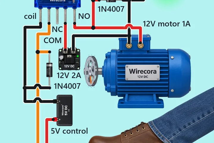 Next step: adds a relayFoot pedal motor switch with a 5 V relay and a 12 V motorStep on the pedal and the 12 V motor runs and the green RUN lamp lights.
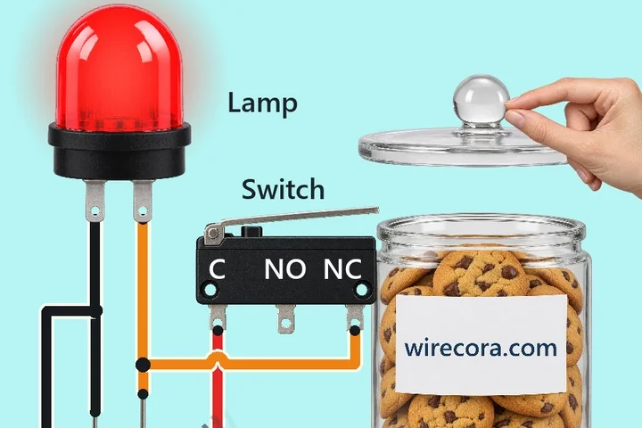 Something new: a buzzerCookie jar lid alarmA little lever under the glass lid keeps this cookie jar quiet.