LED chaser with three transistors
Turning the knob anticlockwise speeds up the running light on nine LEDs, from about 0.5 s to 0.2 s per step. Turned back, it slows.
- 10 parts
- 6 wiring steps
- No code needed
- 6 V supply
Quick answer
The short version. Every pin is in the full wiring below.What you need
- 4 x AA battery holder, 6 V
- BC547 transistor, three of them, in a ring
- 270 ohm resistor
- 4.7 kohm resistor, one at each transistor's base
- 100 uF 25 V electrolytic capacitor
- 100 uF 25 V electrolytic capacitor for start-up
- 5 mm LED
- 330 ohm resistor, one for each green and red LED
- 68 ohm resistor, one for each blue LED
- 10 kohm linear potentiometer
How to wire it
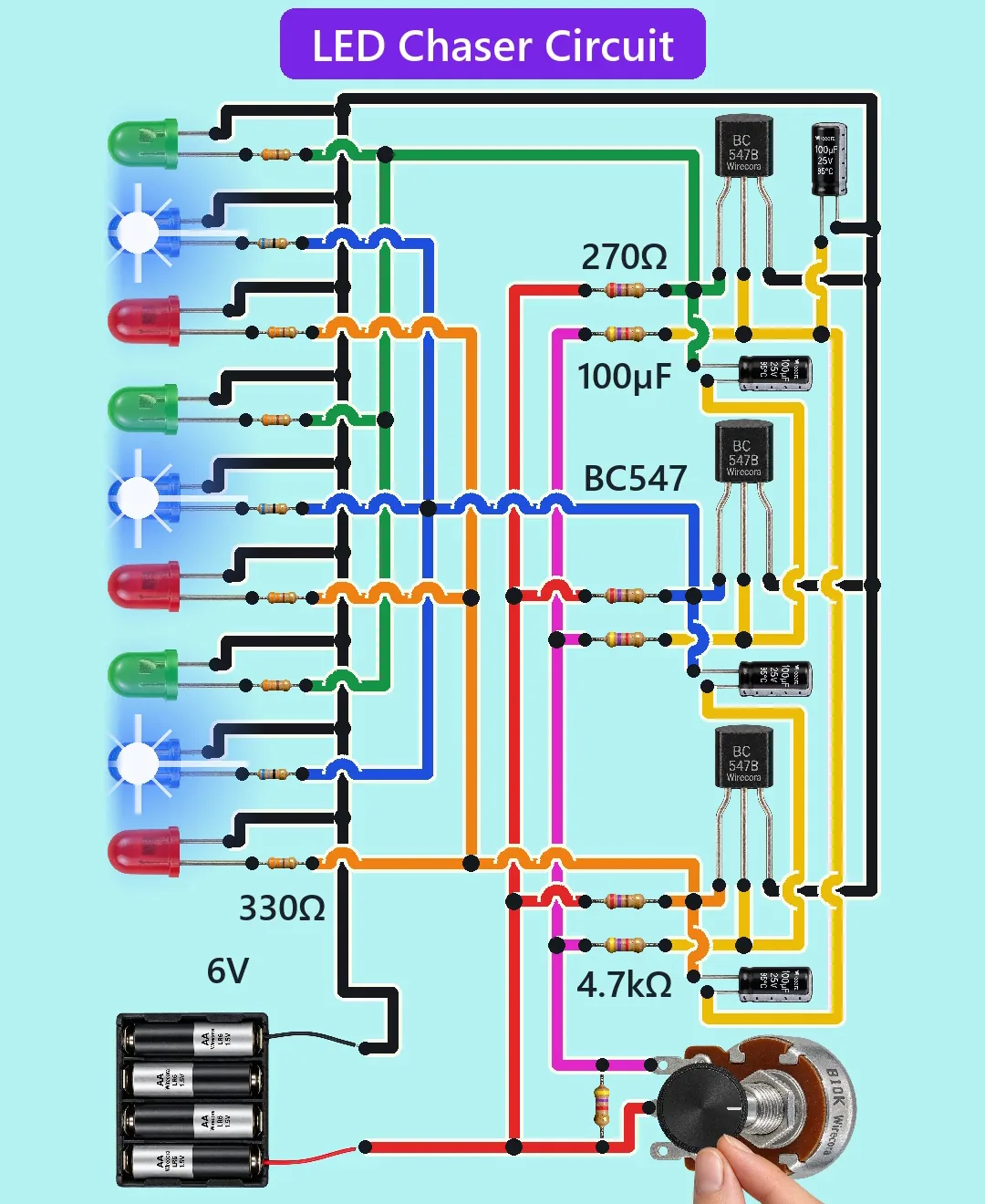
- Each colour group is one transistor's: the 270 ohm resistor from the 6 V rail to that transistor's collector, and the emitter to ground.
- Each of the three LEDs in a group takes the collector node through its own resistor (330 ohm for green and red, 68 ohm for blue) to its anode, with the cathode to ground.
- A 100 uF capacitor from each collector (plus) to the next transistor's base, and from the third collector back to the first base, making the ring.
- Each base gets a 4.7 kohm resistor to the potentiometer's anticlockwise lug.
- Potentiometer wiper to the 6 V rail, with the third lug unused and a 4.7 kohm resistor across the pot.
- The start-up 100 uF capacitor from the first transistor's base (plus) to ground.
Before you power it: 6 V from four AA cells, about 58 mA. Keep a resistor with every LED.
Parts list
- 4 x AA battery holder, 6 V
- BC547 transistor, three of them, in a ring
- 270 ohm resistor, one at each transistor's collector
- 4.7 kohm resistor, one at each transistor's base
- 100 uF 25 V electrolytic capacitor, three of them, each coupling one collector to the next base (plus on the collector)
- 100 uF 25 V electrolytic capacitor for start-up, from the first transistor's base (plus) to ground
- 5 mm LED, nine of them: three green, three blue, three red
- 330 ohm resistor, one for each green and red LED
- 68 ohm resistor, one for each blue LED
- 10 kohm linear potentiometer, used as a variable resistor, with a 4.7 kohm resistor across it
Wiring, step by step
- Each colour group is one transistor's: the 270 ohm resistor from the 6 V rail to that transistor's collector, and the emitter to ground.
- Each of the three LEDs in a group takes the collector node through its own resistor (330 ohm for green and red, 68 ohm for blue) to its anode, with the cathode to ground.
- A 100 uF capacitor from each collector (plus) to the next transistor's base, and from the third collector back to the first base, making the ring.
- Each base gets a 4.7 kohm resistor to the potentiometer's anticlockwise lug.
- Potentiometer wiper to the 6 V rail, with the third lug unused and a 4.7 kohm resistor across the pot.
- The start-up 100 uF capacitor from the first transistor's base (plus) to ground.
How it works
- Three BC547 transistors in a ring flip on and off one after another, because each collector drives the next base through a capacitor.
- A colour group lights while its transistor is off. The transistor that is on pulls its collector low and shorts its LEDs, so they go dark.
- So the light runs green, blue, red down the column, over and over.
- The pot sets the base current, so it sets the speed. Steps take about 0.5 s at mid travel, 0.2 s fully anticlockwise and 0.55 s fully clockwise.
- Every LED has its own resistor and carries about 3.5 mA (4 mA with fresh cells); the battery gives about 58 mA.
What the video simplifies
- The LED glow size, starburst and equal brightness are drawn: real green and red LEDs are dim at 3.5 mA, and blue is brighter.
- The fingers stay on the knob through a 150 degree turn, and the click and ratchet sounds are added. The circuit is silent. The chase is already running at the start, so power-up is not shown.
- The step timing while the knob turns follows a simplified model, within about 10 % of the full simulation.
- The start-up capacitor and the 4.7 kohm across the pot are added by us: in simulation a perfectly matched ring sticks with every LED off at switch-on, and the pot alone stalls at the slow end. The original used a 9 V battery; this one uses 6 V and a green, blue, red order.
- The original put three LEDs in parallel on one shared 330 ohm resistor; here every LED has its own resistor.
- This was checked by ngspice simulation and datasheets, not built.
You found this by searching. Here's the whole path.
- Read how it works
- See it work
- Build it
- Show it
Next: see it work
Thirty seconds of video shows the circuit doing its job.
Then build it
6 V from four AA cells, about 58 mA. Keep a resistor with every LED.
Then show it
Built it, or stuck halfway? Post a photo in the Wirecora Discord. Questions get an answer every day.
What to build next
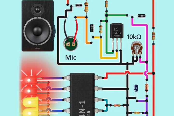 Similar partsMusic VU meter with LM3914An LM3914 drives a bar of ten LEDs from a small microphone, so the tower jumps with every bass kick.
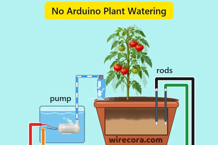 Something new: a pumpSelf-watering plant with one MOSFET (no Arduino)Two steel rods in the soil decide when the pump runs.
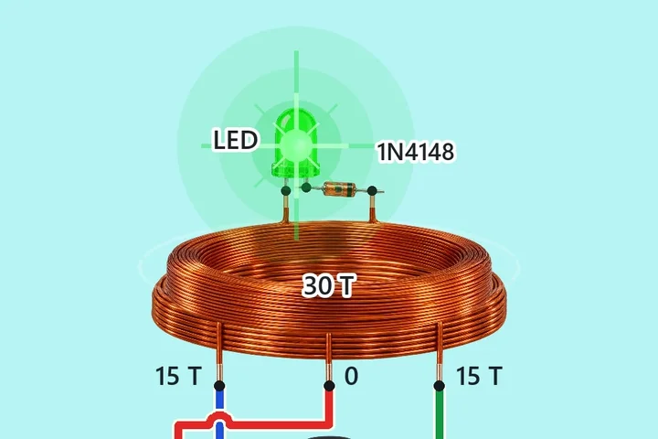 Similar partsWireless power transfer with one transistorOne BC547 makes a coil oscillate at about 1 to 1.2 MHz.