Wireless power transfer with one transistor
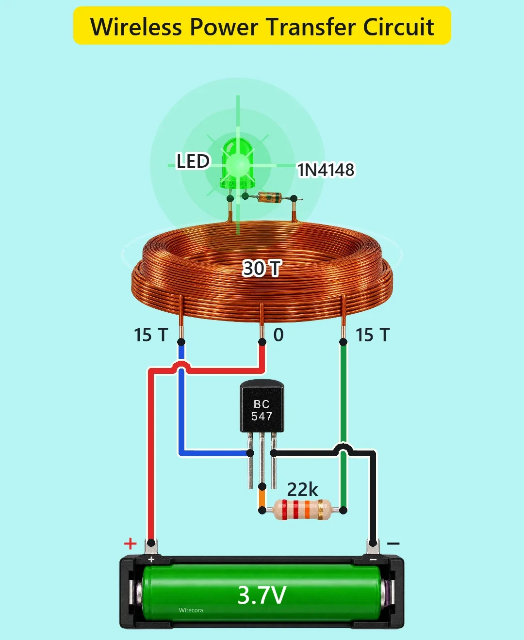
One BC547 makes a coil oscillate at about 1 to 1.2 MHz. A second 30-turn coil with a green LED lights up when you bring it close, with no wire between the two. The range is millimetres to about 3 cm.
- 6 parts
- 7 wiring steps
- No code needed
- 3.7 V supply
Quick answer
The short version. Every pin is in the full wiring below.What you need
- BC547 transistor
- 22k resistor
- 3.7 V 18650 Li-ion cell in a holder
- Transmitter coil: one continuous winding of 30 turns of 0.5 mm enamelled wire
- Receiver coil: 30 turns
- Green LED and a 1N4148 diode
How to wire it
- Wind the transmitter as one winding with a lead at turn 1, turn 15 (the tap) and turn 30.
- Battery plus goes to the centre tap of the transmitter coil.
- One end of the transmitter coil (turn 1) goes to the BC547 collector.
- The other end (turn 30) goes through the 22k resistor to the BC547 base.
- The BC547 emitter goes to battery minus.
- The BC547 pins are C, B, E from left to right with the flat face toward you.
- Receiver: the LED anode goes to the start of the receiver coil.
Before you power it: Low voltage only (3.7 V). A Li-ion cell can give a very large current into a short, so use a protected cell and keep the bare wires apart. The circuit radiates radio noise near 1 MHz, so keep it short-lived and do not use it near radio equipment.
Parts list
- BC547 transistor (use a BC547A or BC547B)
- 22k resistor
- 3.7 V 18650 Li-ion cell in a holder (a protected cell)
- Transmitter coil: one continuous winding of 30 turns of 0.5 mm enamelled wire (about 90 µH), tapped at turn 15
- Receiver coil: 30 turns (about 90 µH)
- Green LED and a 1N4148 diode
Wiring, step by step
- Wind the transmitter as one winding with a lead at turn 1, turn 15 (the tap) and turn 30. Wind it all in the SAME direction. A half wound the other way does not oscillate.
- Battery plus goes to the centre tap of the transmitter coil.
- One end of the transmitter coil (turn 1) goes to the BC547 collector.
- The other end (turn 30) goes through the 22k resistor to the BC547 base.
- The BC547 emitter goes to battery minus.
- The BC547 pins are C, B, E from left to right with the flat face toward you.
- Receiver: the LED anode goes to the start of the receiver coil. The LED cathode goes to the 1N4148 anode, and the 1N4148 band end goes to the end of the coil. The LED and the diode are in series.
How it works
- Current flows from the tap into both halves of the winding and the collector half carries the transistor current. The two halves are coupled, so a rising collector current pushes the base end up and drives more base current through the 22k. This feedback switches the transistor on harder.
- As the current peaks, the feedback reverses and the transistor switches off. The coil then swings back and the cycle repeats about a million times a second. The simulation gives 1.2 MHz with the receiver near and about 1.07 MHz with it away.
- The changing magnetic field of the transmitter coil induces a voltage in the receiver coil. When the receiver is close the voltage is large enough (a few volts) to light the LED. The 1N4148 in series protects the LED from the reverse voltage.
- Move the receiver away and the induced voltage falls with distance. In the simulation the LED current falls from about 1.5 mA at 5 mm to 0.4 mA at 12 mm and to 0.1 mA at 25 mm. Beyond 30 to 40 mm it is too dim to see.
- The 22k base resistor is matched to this coil. A coil 30 % smaller needs about 15 kΩ, and very small coils will not start.
What the video simplifies
- This circuit was simulated in ngspice and in a second hand-written model. It was not measured on hardware. The two models agree on the order of size but not exactly: for example the peak collector current is 50 mA in one and 65 mA in the other.
- The hand-free movement of the receiver, its scale, the LED glow and brightness, the faint field rings and the sound are dramatised. The real LED current is 0.1 to 1.8 mA, and a green LED at that current is dim in daylight.
- Only about 3 mW reaches the LED. It cannot run a high-power load or charge a phone.
- The popular version of this circuit puts 1k on the base. In our simulation that pulls 340 to 410 mA peaks through a BC547 (limit 200 mA), and its bare LED sees 6.5 to 8.7 V reverse voltage (limit 5 V). Here it is 22k and a 1N4148 in series with the LED.
- In the simulation, very high-gain parts (BC547C, or gain above about 450) do not start, so use a BC547A or B. Both halves must be coupled closely, so wind them in one go on one former.
- The cell has no fuse or short-circuit protection of its own, so use a protected cell. The circuit draws about 30 mA while connected and it radiates radio noise near 1 MHz.
You found this by searching. Here's the whole path.
- Read how it works
- See it work
- Build it
- Show it
Thirty seconds of video shows the circuit doing its job.
Low voltage only (3.7 V). A Li-ion cell can give a very large current into a short, so use a protected cell and keep the bare wires apart. The circuit radiates radio noise near 1 MHz, so keep it short-lived and do not use it near radio equipment.
Built it, or stuck halfway? Post a photo in the Wirecora Discord. Questions get an answer every day.
What to build next
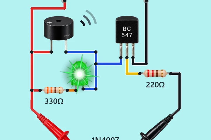 Similar partsContinuity and diode tester with a BC547 and a buzzerTouch the two probes to a wire, a good fuse, or a diode with its band towards the black probe: the buzzer beeps and the green LED lights.
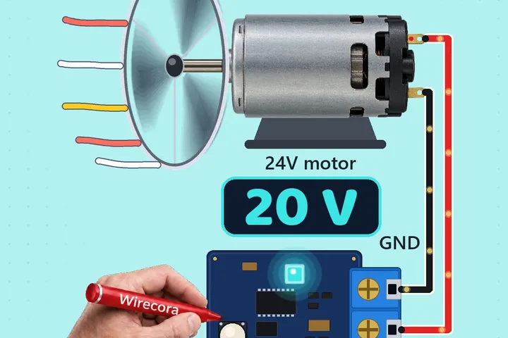 Something new: a motorUSB-C PD trigger board, 5 V to 20 VA USB-C charger gives 5 V until something asks for more.
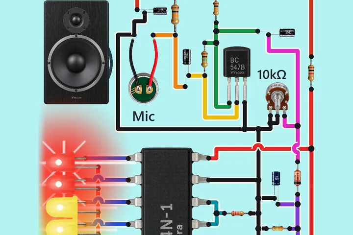 Similar partsMusic VU meter with LM3914An LM3914 drives a bar of ten LEDs from a small microphone, so the tower jumps with every bass kick.