USB-C PD trigger board, 5 V to 20 V
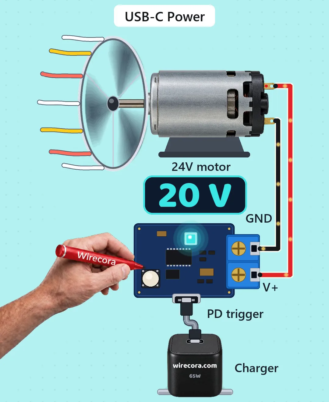
A USB-C charger gives 5 V until something asks for more. Press the trigger board's button and it asks for 9 V, then 15 V, then 20 V, and the motor on its screws speeds up at every step. One more press goes back to 5 V.
- 4 parts
- 4 wiring steps
- No code needed
- 20 V supply
Quick answer
The short version. Every pin is in the full wiring below.What you need
- USB-C PD charger, 65 W, 5 V to 20 V
- USB-C cable rated 3 A
- ZY12PDN USB-C PD trigger board
- 24 V DC motor, RS-385 class
How to wire it
- Charger to the trigger board's USB-C socket with the 3 A USB-C cable.
- Board V+ screw to the motor's + tab (red wire).
- Board GND screw to the motor's other tab (black wire).
- Nothing else: no transistor, no relay and no diode.
Before you power it: USB-C power at up to 20 V and 3 A. Set the voltage before you connect a 12 V device: 20 V will burn it. Use a fan guard: at 20 V the blade tips move at about 30 m/s.
Parts list
- USB-C PD charger, 65 W, 5 V to 20 V (the Short uses an ASUS AC65-00: 5 V, 9 V and 15 V at 3 A, 20 V at 3.25 A, no 12 V)
- USB-C cable rated 3 A
- ZY12PDN USB-C PD trigger board (screw terminals V+ and GND; Joy-it COM-ZY12PDN-ST: 5, 9, 12, 15 or 20 V by its button, an RGB LED, up to 20 V and 100 W in, 5 A out)
- 24 V DC motor, RS-385 class (made for 12 to 30 V, about 7,500 rpm at 24 V), with a small fan blade
Wiring, step by step
- Charger to the trigger board's USB-C socket with the 3 A USB-C cable. The board and the charger talk over the cable's CC wire.
- Board V+ screw to the motor's + tab (red wire).
- Board GND screw to the motor's other tab (black wire).
- Nothing else: no transistor, no relay and no diode. The motor runs straight from the board's screws.
How it works
- Plugged in, the charger gives 5 V, as a USB-C charger does until something asks for more. The motor turns slowly, at about 1,300 rpm with the fan.
- Each press of the button makes the board ask the charger, in USB Power Delivery over the CC wire, for the next voltage it offers: 9 V, then 15 V, then 20 V. The charger switches its output and the board passes it to its screws.
- The motor speeds up at every step: about 2,600 rpm at 9 V, 4,500 rpm at 15 V and 6,000 rpm at 20 V. At 20 V it takes about 0.15 A, and even held still about 2 A, inside the charger's 3 A and the cable's 3 A.
- One more press at 20 V goes back to 5 V. The LED changes colour at every step (red, yellow, green, aqua with this charger); the colour is the board's code for the step, not a voltmeter.
- A charger that also offers 12 V adds that step, and the board stops there too. Many 20 W phone chargers stop at 9 V, so they cannot give 15 V or 20 V.
What the video simplifies
- The board is drawn larger than life, about 1.4 times the motor's scale.
- The fan speeds come from the motor's listing and a model, not a measurement, and the fan load is an estimate. The drawn fan turns much slower than the real one, which makes about 22 to 100 turns a second.
- How fast the motor speeds up and slows down at each step is an estimate. How far the ribbons lift at each step is a drawing choice.
- The motor picture is a bigger 775-size brushed motor standing in for the smaller RS-385 (the same type, with two terminals).
- A big drill motor in its place would take far more current at start-up and trip the charger. That is why this one is a small RS-385 class motor.
- This circuit was checked with datasheets and listings, not built.
You found this by searching. Here's the whole path.
- Read how it works
- See it work
- Try it on the board
- Build it
- Show it
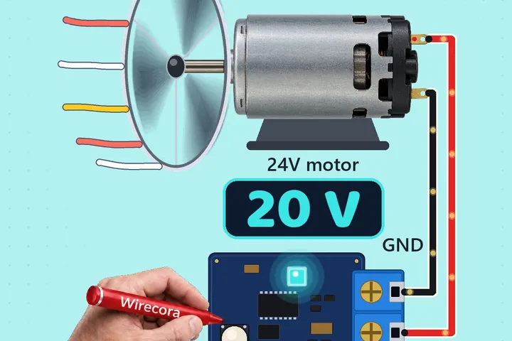
Thirty seconds of video shows the circuit doing its job. Then this whole circuit is on the wiring board. Wire it there first and watch it work before you touch a real part.
USB-C power at up to 20 V and 3 A. Set the voltage before you connect a 12 V device: 20 V will burn it. Use a fan guard: at 20 V the blade tips move at about 30 m/s.
Built it, or stuck halfway? Post a photo in the Wirecora Discord. Questions get an answer every day.
What to build next
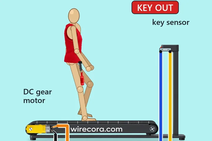 Same motorTreadmill safety key stop with an Arduino Nano, a reed switch and a 5 V relayA runner jogs on a small model treadmill with a red magnet key clipped from their top to the console.
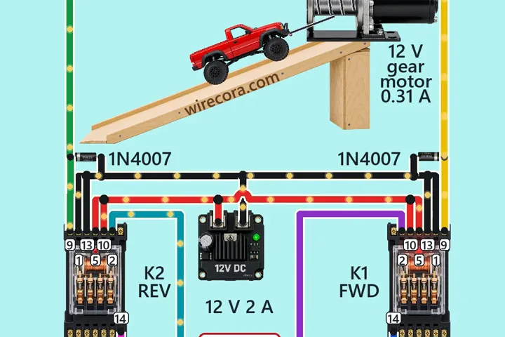 Next step: adds a relayWinch with an interlockHold FORWARD and the winch pulls the car up the ramp.
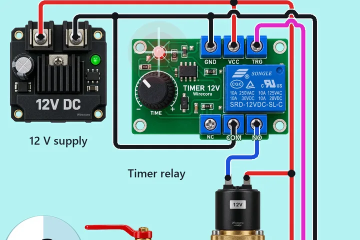 Something new: a timer relayAutomatic water filling systemPut a bottle under the tap: the sensor sees it, the timer relay closes, the solenoid valve opens and water runs.