Music VU meter with LM3914
An LM3914 drives a bar of ten LEDs from a small microphone, so the tower jumps with every bass kick. Louder sound lights more LEDs, from the bottom up.
- 15 parts
- 8 wiring steps
- No code needed
- 9 V supply
Quick answer
The short version. Every pin is in the full wiring below.What you need
- 9 V battery
- LM3914 LED bar driver, PDIP-18
- BC547B transistor
- 1N4148 diode
- Electret microphone capsule
- 5 mm LED
- 10 kohm linear potentiometer
- 10 uF 25 V capacitor
- 100 uF 25 V capacitor
- 1 uF 50 V capacitor
- 10 kohm resistor, two of them
- 1 Mohm resistor
- 330 kohm resistor
- 2.2 kohm resistor
- 1 kohm resistor
How to wire it
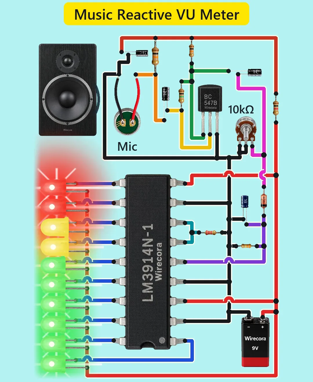
- Battery plus to LM3914 pin 3 (V+), and its own wire to pin 9 (MODE) for bar mode.
- Battery plus through the 1 kohm resistor to a filtered supply line with the 100 uF capacitor to ground.
- Mic output lead through a 10 kohm resistor from the filtered supply, and through a 10 uF capacitor to the BC547's base.
- BC547: 1 Mohm from collector to base, a 10 kohm collector resistor to the filtered supply, and the emitter to ground.
- BC547 collector through a 10 uF capacitor to the 1N4148's anode, and from there through the 10 kohm pot to ground (sensitivity).
- 1N4148 cathode to a node holding the 1 uF capacitor to ground, a 330 kohm resistor to ground and LM3914 pin 5 (SIG).
- LM3914 pin 7 (REF OUT) to pin 6 (RHI) and through the 2.2 kohm resistor to ground.
- Ten LEDs: each anode to the +9 V line, each cathode to the LM3914 output.
Before you power it: 9 V battery only, up to about 71 mA. Keep the 2.2 kohm resistor on REF OUT: it sets the LED current.
Parts list
- 9 V battery (PP3)
- LM3914 LED bar driver, PDIP-18
- BC547B transistor (the microphone preamp)
- 1N4148 diode (the peak detector)
- Electret microphone capsule
- 5 mm LED, ten of them: six green, two yellow and two red
- 10 kohm linear potentiometer, used as a variable resistor (sensitivity)
- 10 uF 25 V capacitor, two of them, one at the mic and one after the preamp
- 100 uF 25 V capacitor (supply filter)
- 1 uF 50 V capacitor (peak detector)
- 10 kohm resistor, two of them (mic bias and preamp collector)
- 1 Mohm resistor (preamp, collector to base)
- 330 kohm resistor (peak detector)
- 2.2 kohm resistor (on REF OUT, sets the LED current)
- 1 kohm resistor (supply filter)
Wiring, step by step
- Battery plus to LM3914 pin 3 (V+), and its own wire to pin 9 (MODE) for bar mode. Battery minus to pin 2 (V-), pin 4 (RLO) and pin 8 (REF ADJ).
- Battery plus through the 1 kohm resistor to a filtered supply line with the 100 uF capacitor to ground. This supply powers the mic and the preamp, so the changing LED current stays out of it.
- Mic output lead through a 10 kohm resistor from the filtered supply, and through a 10 uF capacitor to the BC547's base. The mic's ground lead goes to ground.
- BC547: 1 Mohm from collector to base, a 10 kohm collector resistor to the filtered supply, and the emitter to ground.
- BC547 collector through a 10 uF capacitor to the 1N4148's anode, and from there through the 10 kohm pot to ground (sensitivity).
- 1N4148 cathode to a node holding the 1 uF capacitor to ground, a 330 kohm resistor to ground and LM3914 pin 5 (SIG).
- LM3914 pin 7 (REF OUT) to pin 6 (RHI) and through the 2.2 kohm resistor to ground.
- Ten LEDs: each anode to the +9 V line, each cathode to the LM3914 output. LED1 is on pin 1, and LED2 to LED10 are on pins 18 to 10.
How it works
- The mic is biased through a 10 kohm from the filtered supply and feeds a one-transistor BC547 preamp. The 1 Mohm from collector to base sets its gain at about 100.
- The 10 kohm pot to ground sets the sensitivity: it is most sensitive at its full 10 kohm, with the shaft fully anticlockwise.
- The 1N4148, the 1 uF capacitor and the 330 kohm resistor catch the peaks and let them fall in about a third of a second.
- The LM3914 compares that level with its 1.25 V reference in ten steps of 0.125 V and lights the bar from the bottom up. The 2.2 kohm on REF OUT sets about 6.7 mA per LED.
- The speaker only plays the music. It is not wired to the circuit.
What the video simplifies
- The bar in the video shows the simulated pin 5 voltage of this circuit with the video's own soundtrack at the mic. The beat was mixed so its kicks, snare roll and bass drop light the bar this way.
- That needs loud music close to the mic (peaks of 2.5 to 5 Pa, about 100 to 105 dB SPL) with the pot at its full 10 kohm. The height also varies with the transistor and the mic.
- The glow, sound rings and speaker pulse are drawn, and the sound is synthesised.
- This was checked by simulation and datasheets, not built.
You found this by searching. Here's the whole path.
- Read how it works
- See it work
- Build it
- Show it
Next: see it work
Thirty seconds of video shows the circuit doing its job.
Then build it
9 V battery only, up to about 71 mA. Keep the 2.2 kohm resistor on REF OUT: it sets the LED current.
Then show it
Built it, or stuck halfway? Post a photo in the Wirecora Discord. Questions get an answer every day.
What to build next
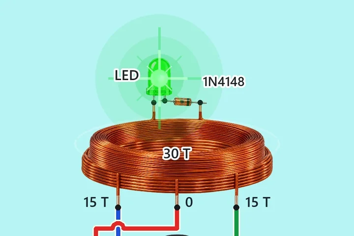 Similar partsWireless power transfer with one transistorOne BC547 makes a coil oscillate at about 1 to 1.2 MHz.
 Something new: a pumpSelf-watering plant with one MOSFET (no Arduino)Two steel rods in the soil decide when the pump runs.
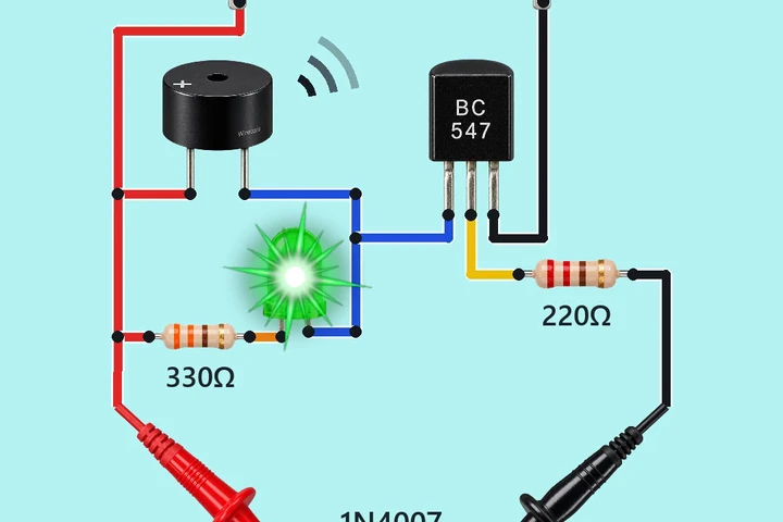 Similar partsContinuity and diode tester with a BC547 and a buzzerTouch the two probes to a wire, a good fuse, or a diode with its band towards the black probe: the buzzer beeps and the green LED lights.