LED flasher with adjustable speed
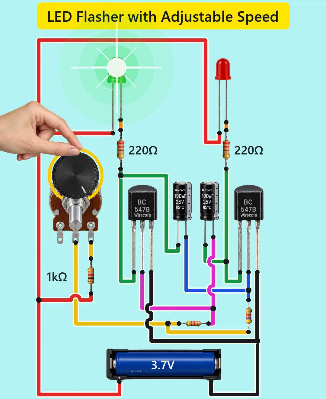
Two LEDs, one green and one red, take turns: exactly one is lit at a time and they swap again and again. Turn the knob clockwise and they swap faster, turn it back and they slow down. In the Short the swapping runs at about 1.6 times a second with the knob fully clockwise and about 0.6 times a second fully counter-clockwise.
- 10 parts
- 8 wiring steps
- No code needed
Quick answer
The short version. Every pin is in the full wiring below.What you need
- 18650 Li-ion cell in a holder
- BC547B NPN transistor, two of them
- 5 mm green LED
- 5 mm red LED
- 220 ohm resistor
- 100 uF 25 V electrolytic capacitor, two of them
- 4.7 k resistor
- 1 k resistor, in series with the potentiometer
- 10 k linear rotary potentiometer
- Jumper wires
How to wire it
- Cell plus to the anode (longer lead) of the green LED, the anode of the red LED, and one end of the 1 k resistor.
- Cell minus to the emitter (E, right leg) of both BC547B transistors.
- Green LED cathode to one end of a 220 ohm resistor.
- Red LED cathode to one end of the other 220 ohm resistor.
- Capacitor 1 minus lead (striped side) to transistor 2's base (B, middle leg) and to one end of a 4.7 k resistor.
- Capacitor 2 minus lead (striped side) to transistor 1's base (B, middle leg) and to one end of the other 4.7 k resistor.
- The free ends of both 4.7 k resistors to the potentiometer's middle lug (the wiper).
- Potentiometer right lug (terminal 3, clockwise end) to the free end of the 1 k resistor.
Before you power it: Everything runs from one 3.7 V cell. Check the cell's plus and minus before you connect it, put the capacitors in the right way round (the stripe is minus), and never short the cell, because a Li-ion cell can get very hot and catch fire.
Parts list
- 18650 Li-ion cell in a holder (3.7 V, 3.0 V when empty to 4.2 V full)
- BC547B NPN transistor, two of them (flat face toward you, the legs left to right are C, B, E)
- 5 mm green LED (the longer lead is the anode)
- 5 mm red LED (the longer lead is the anode)
- 220 ohm resistor, two of them, one in series with each LED
- 100 uF 25 V electrolytic capacitor, two of them (the stripe marks the minus lead)
- 4.7 k resistor, two of them, one to each transistor base
- 1 k resistor, in series with the potentiometer
- 10 k linear rotary potentiometer (B10K), with a knob
- Jumper wires
Wiring, step by step
- Cell plus to the anode (longer lead) of the green LED, the anode of the red LED, and one end of the 1 k resistor.
- Cell minus to the emitter (E, right leg) of both BC547B transistors.
- Green LED cathode to one end of a 220 ohm resistor. The other end of that resistor goes to transistor 1's collector (C, left leg) and to the plus lead of capacitor 1.
- Red LED cathode to one end of the other 220 ohm resistor. The other end of that resistor goes to transistor 2's collector (C, left leg) and to the plus lead of capacitor 2.
- Capacitor 1 minus lead (striped side) to transistor 2's base (B, middle leg) and to one end of a 4.7 k resistor. Each capacitor feeds the other transistor, which is what makes the two take turns.
- Capacitor 2 minus lead (striped side) to transistor 1's base (B, middle leg) and to one end of the other 4.7 k resistor.
- The free ends of both 4.7 k resistors to the potentiometer's middle lug (the wiper).
- Potentiometer right lug (terminal 3, clockwise end) to the free end of the 1 k resistor. The left lug (terminal 1) stays unconnected, so the pot works as a variable resistor between its middle and right lugs.
How it works
- The two transistors work as switches that flip each other: while one is on, its LED is lit and the other transistor is off with its LED dark.
- The lit side's capacitor holds the other transistor's base pushed below the emitter voltage, so that transistor stays off. The 4.7 k resistors, fed through the 1 k resistor and the potentiometer, slowly charge the capacitor back up.
- When a base reaches about 0.7 V its transistor turns on. Its collector drops and the capacitor passes that drop to the other base, which switches the other transistor off. The LEDs swap and the cycle starts again.
- Turning the knob clockwise lowers the resistance between the pot's wiper and clockwise lug, from 10 k down to 0. The capacitors then recharge faster and the LEDs swap faster, about 1.6 times a second at the fast end and about 0.6 times a second at the slow end.
- With the 3.7 V cell each LED gets about 8 mA. The transistor bases swing down to about -1.5 V, well inside the BC547's 6 V limit, and each capacitor sees a small reverse voltage (under 1 V) for part of every cycle, which is normal in this circuit.
What the video simplifies
- This circuit was checked by simulation (ngspice) and against the datasheets, not built.
- The glow around the LEDs, the short fade at each swap and the sounds are graphics and sound effects, not part of the circuit.
- In the Short the speed follows the knob instantly. A real circuit changes speed within a cycle or two as the capacitors settle.
- The hand turns the knob in three quick twists; the one-finger turn of the first cut was replaced for this version.
- The original viral version used a CD4047 chip. This one uses two transistors and no chip, with values chosen so it keeps flashing at every knob position.
- The 4.7 k resistors are drawn small and without labels; their colour bands (yellow, violet, red, gold) are correct.
- The knob hides the B10K marking on the potentiometer; use a 10 k linear one.
- The speeds and currents are for a 3.7 V cell. At 3.0 V (empty) the ends are about 1.9 and 0.7 flashes per second at 5 mA per LED, and at 4.2 V (full) about 1.5 and 0.6 at 10 mA per LED; they are simulated values, not measured.
You found this by searching. Here's the whole path.
- Read how it works
- See it work
- Build it
- Show it
Thirty seconds of video shows the circuit doing its job.
Everything runs from one 3.7 V cell. Check the cell's plus and minus before you connect it, put the capacitors in the right way round (the stripe is minus), and never short the cell, because a Li-ion cell can get very hot and catch fire.
Built it, or stuck halfway? Post a photo in the Wirecora Discord. Questions get an answer every day.
What to build next
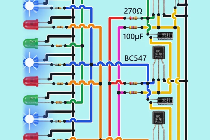 Similar partsLED chaser with three transistorsTurning the knob anticlockwise speeds up the running light on nine LEDs, from about 0.5 s to 0.2 s per step.
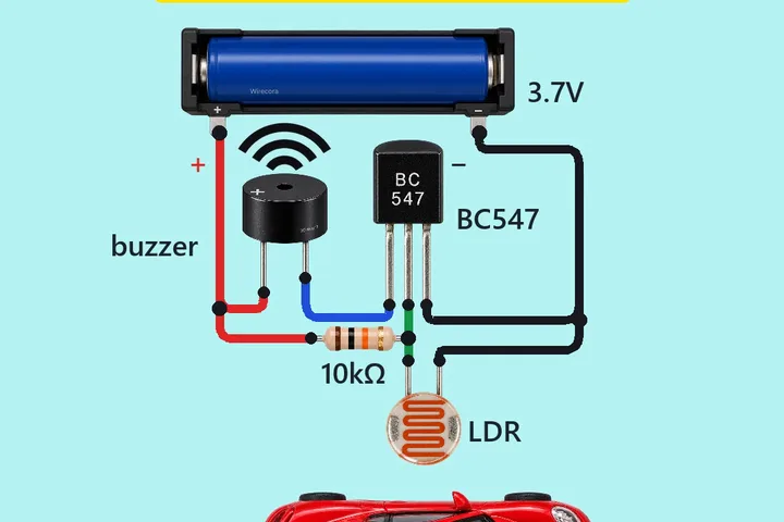 Something new: a light sensorLaser tripwire alarmA red laser shines on a light sensor and the buzzer stays quiet.
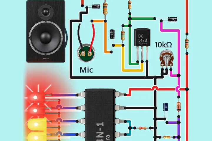 Similar partsMusic VU meter with LM3914An LM3914 drives a bar of ten LEDs from a small microphone, so the tower jumps with every bass kick.