Automatic pet feeder with an Arduino Nano, an IR sensor and a servo flap
A dog, then a cat, walk up to the bowl. An infrared sensor sees the head, and the Arduino Nano swings a servo flap open to drop one portion of food, then closes it. One portion per visit.
- 5 parts
- 6 wiring steps
- Arduino code
- 5 V supply
Quick answer
The short version. Every pin is in the full wiring below.What you need
- Arduino Nano
- FC-51 infrared obstacle sensor module
- SG90 micro servo
- Regulated 5 V 2 A supply
- A hopper with a flap on the servo horn
How to wire it
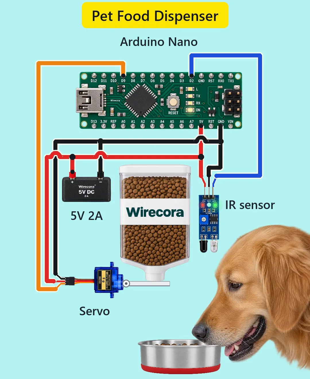
- Supply + to the Nano 5V pin, the sensor VCC and the servo red lead.
- Supply minus to the Nano GND pin, the sensor GND and the servo brown lead.
- Sensor OUT to Nano D2.
- Nano VIN and USB are not used while the supply is connected.
- Set the sensor's trimmer so it sees the pet's head but not the bowl below it.
- If the Nano resets when the servo moves, add a 470 uF capacitor across the servo supply.
Before you power it: Everything runs on 5 V from a regulated supply. Keep the flap and servo out of reach of paws and noses while testing.
Parts list
- Arduino Nano (5 V)
- FC-51 infrared obstacle sensor module (2 to 30 cm, output LOW while something is in front of it)
- SG90 micro servo (4.8 to 6 V; brown = GND, red = +, orange = signal)
- Regulated 5 V 2 A supply
- A hopper with a flap on the servo horn, and a bowl
Wiring, step by step
- Supply + to the Nano 5V pin, the sensor VCC and the servo red lead.
- Supply minus to the Nano GND pin, the sensor GND and the servo brown lead.
- Sensor OUT to Nano D2. Servo orange lead (signal) to Nano D9.
- Nano VIN and USB are not used while the supply is connected.
- Set the sensor's trimmer so it sees the pet's head but not the bowl below it. Dark fur is seen from a shorter distance, and direct sunlight disturbs the sensor.
- If the Nano resets when the servo moves, add a 470 uF capacitor across the servo supply.
How it works
- The FC-51 pulls OUT LOW while something is within its range. The sketch reads D2 every 20 ms; when it sees LOW and has not fed this visit, it opens the flap from 0 to 80 degrees in 20 steps of 10 ms (0.20 s), waits 550 ms and closes it again.
- The flag fed stays true until OUT goes HIGH again, so a pet that stays gets only one portion, and the next pet gets its own.
- The flap sweep of 80 degrees in 0.20 s is 400 degrees per second, against the SG90's 600 degrees per second.
- The sensor's output is HIGH (5 V, through the module's 10 k pull-up) when clear and about 0.2 V when triggered. The Nano reads above 3.0 V as high and below 1.5 V as low, so both are clear.
- Supply current in the worst case, with the servo stalled, is about 0.71 A (servo about 0.65 A, Nano about 19 mA, sensor about 43 mA), against 2 A.
The code: pet_feeder.ino
The Arduino code for this circuit is in the Wirecora Discord, in the channel #arduino-code (owner’s choice, 14 October 2026: the code lives where you can ask about it). It is a plain .ino file you can download there.
The sketch the Short was animated from, run step by step in a simulation; it has not been run on a real board. It uses the standard Servo library.
What the video simplifies
- The pets eat in about a second and take turns every 3 seconds.
- The kibble starts and stops cleanly, and the stream ends a moment before the flap swings back. A real flap cuts through the kibble and gives rough portions; real feeders use an auger or a drum.
- The hopper level does not fall.
- The electronics are drawn much larger than the pets, the bowl and the hopper, and the sensor is drawn face-on although it looks down.
- The sensor also has the bowl in its range, so it only works with the trimmer set between the head and the bowl.
- Nothing limits how often a pet comes back.
- This circuit was checked by datasheets and calculation, not built.
You found this by searching. Here's the whole path.
- Read how it works
- See it work
- Try it on the board
- Build it
- Show it
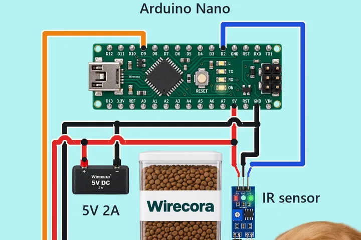
Thirty seconds of video shows the circuit doing its job. Then this whole circuit is on the wiring board. Wire it there first and watch it work before you touch a real part.
Everything runs on 5 V from a regulated supply. Keep the flap and servo out of reach of paws and noses while testing.
Built it, or stuck halfway? Post a photo in the Wirecora Discord. Questions get an answer every day.
What to build next
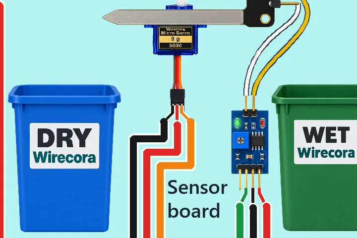 Same Arduino + servoAutomatic wet and dry waste sorter with an Arduino NanoA dry plastic bottle tips into the DRY bin, a damp banana peel into the WET bin.
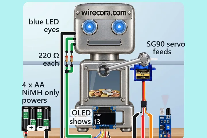 Next step: adds a displayCoin-eating robot bank with an Arduino Nano, an FC-51 IR sensor, an SG90 servo and an OLED counterSet a coin on the robot's scoop.
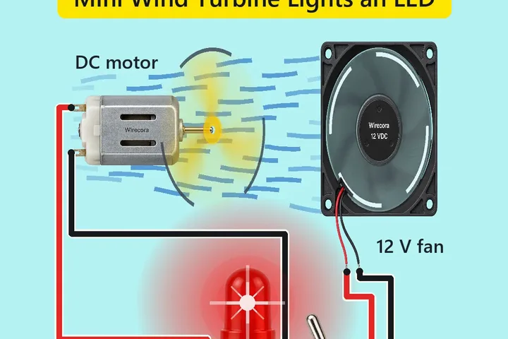 Something new: a motorMini wind turbine that lights an LED: a 12 V fan, a motor and a 100 ohm resistorA 12 V fan blows on a propeller fixed to a small DC motor.