Mini wind turbine that lights an LED: a 12 V fan, a motor and a 100 ohm resistor
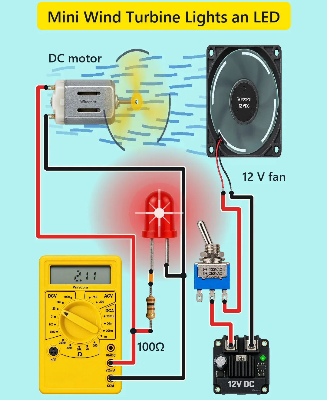
A 12 V fan blows on a propeller fixed to a small DC motor. The motor works as a generator and lights a red LED through a 100 ohm resistor, while a meter reads about 2.1 V. A toggle switches the fan on and off.
- 8 parts
- 5 wiring steps
- No code needed
- 12 V supply
Quick answer
The short version. Every pin is in the full wiring below.What you need
- 12 V DC supply rated at least 0.4 A
- SPDT mini toggle switch
- High-speed 80 mm 12 V DC fan
- 130-size brushed DC motor
- Small 3-blade propeller on the motor shaft
- 100 ohm 1/4 W resistor
- 5 mm red LED
- Digital multimeter on DC V 20
How to wire it
- Fan side: supply + (left screw) to the toggle's centre lug.
- Generator side: one motor terminal through the 100 ohm resistor to the LED's long leg (anode).
- Meter on DC V 20: red lead (V ohm mA jack) on the resistor side, black lead (COM) on the other motor terminal.
- The two circuits are separate and linked only by the wind.
- LED dark? Move the fan closer.
Before you power it: Everything is low voltage: a 12 V supply, and the fan draws about 0.36 A. Keep fingers, hair and wires away from the spinning fan and propeller.
Parts list
- 12 V DC supply rated at least 0.4 A
- SPDT mini toggle switch (MTS-102 type; only the centre lug and one outer lug are used)
- High-speed 80 mm 12 V DC fan, about 4800 rpm, 60 CFM, 0.36 A (for example Same Sky CFM-8025V-148-447; red = +, black = -)
- 130-size brushed DC motor (rated 6 V, about 9100 rpm and 70 mA at no load), used as a generator
- Small 3-blade propeller on the motor shaft (modelled 80 mm across)
- 100 ohm 1/4 W resistor (brown, black, brown, gold)
- 5 mm red LED (30 mA maximum, 1.9 V typical at 10 mA)
- Digital multimeter on DC V 20
Wiring, step by step
- Fan side: supply + (left screw) to the toggle's centre lug. One outer lug to the fan's red wire. The other outer lug is left unused. Fan black wire to supply -. Lever tilted left joins the centre lug to the outer lug wired to the fan and turns the fan on; tilted right it joins the unused lug and the fan is off.
- Generator side: one motor terminal through the 100 ohm resistor to the LED's long leg (anode). The LED's short leg (cathode) to the other motor terminal.
- Meter on DC V 20: red lead (V ohm mA jack) on the resistor side, black lead (COM) on the other motor terminal.
- The two circuits are separate and linked only by the wind. Put the propeller a few centimetres in front of the fan.
- LED dark? Move the fan closer. LED dark and the meter reads minus? The propeller turns the other way: swap the two motor wires. A reverse voltage of about 2 V does not harm the LED (rated 5 V).
How it works
- A DC motor turned by the wind makes a voltage, about 0.57 mV per rpm for this motor (12 ohm winding resistance from its stall current). The LED needs about 1.85 V, which is about 3,300 rpm, which takes about 6 m/s of wind.
- The fan gives about 6.2 to 7.6 m/s at the propeller (60 CFM through its 76 mm opening). At 6.5 m/s the model gives about 3,800 rpm, 2.15 V and about 3 mA through the LED, so the meter reads about 2.1 V. ngspice on the drawn circuit agrees (3,779 rpm, 2.14 V, 3.0 mA, meter 2.106 V).
- The 100 ohm resistor protects the LED: without it the LED would reach its 30 mA maximum at about 7 m/s of wind. With it the LED stays below 28 mA even at the motor's rated speed.
- An ordinary 80 mm PC fan (about 33 CFM, 3.4 m/s) will not light the LED: the propeller does not even start to turn.
- Real dynamics: the turbine reaches 90 % speed after about 2.7 s and coasts down in about 2.5 s. The fan draws 0.356 A at 12 V (about 4.3 W); the LED carries about 3 mA.
What the video simplifies
- Spin-up and run-down are shortened (a real turbine takes about 2.7 s to spin up).
- Rotation is drawn slowed with motion blur. The speed arcs and airflow streaks are illustrative.
- The LED glow is brighter than a real 3 mA LED.
- The fan and propeller are squashed to 64 % width and the fan hub is drawn still. Parts are not to scale.
- The 2.11 V reading and the LED current are calculated estimates. Propeller efficiency, motor friction and wind speed are assumptions: a real build can range from no glow to about 12 mA (meter about 1 to 3 V).
- The 12 V module stands for any 12 V DC supply.
- This circuit was checked by calculation, simulation and datasheets, not built.
You found this by searching. Here's the whole path.
- Read how it works
- See it work
- Build it
- Show it
Next: see it work
Thirty seconds of video shows the circuit doing its job.
Then build it
Everything is low voltage: a 12 V supply, and the fan draws about 0.36 A. Keep fingers, hair and wires away from the spinning fan and propeller.
Then show it
Built it, or stuck halfway? Post a photo in the Wirecora Discord. Questions get an answer every day.
What to build next
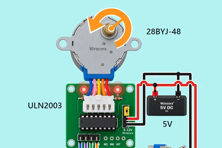 Same motorStepper motor that reverses when you flip a switchFlip the toggle switch and the stepper motor turns the other way.
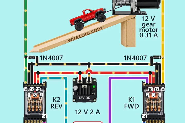 Next step: adds a relayWinch with an interlockHold FORWARD and the winch pulls the car up the ramp.
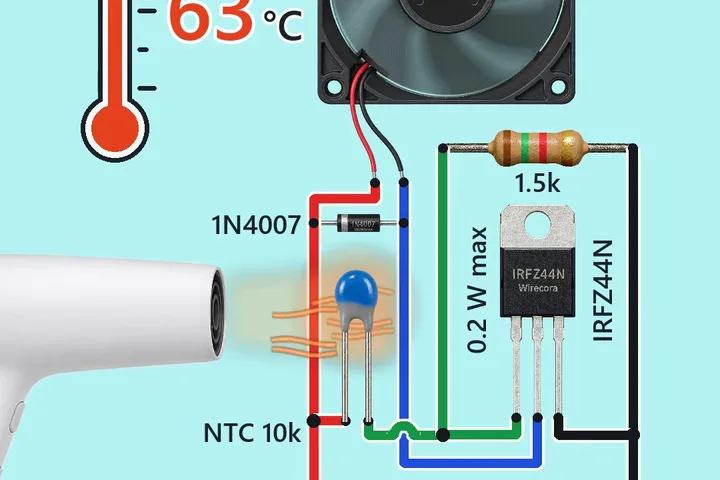 Something new: an MOSFETFan that turns on by itself when it gets hot (NTC thermistor and IRFZ44N MOSFET)A hair dryer warms a 10k NTC thermistor.