Reed switch door alarm
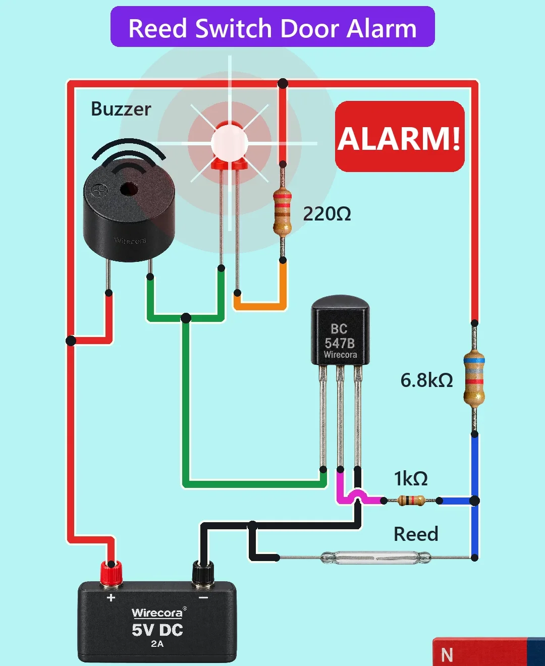
A magnet next to the reed switch means the door is closed, and the circuit is silent. Pull the magnet away and the buzzer sounds and a red LED lights. Put the magnet back and the alarm stops. A BC547 transistor drives the buzzer and the LED.
- 9 parts
- 6 wiring steps
- No code needed
- 5 V supply
Quick answer
The short version. Every pin is in the full wiring below.What you need
- 5 V DC supply
- Glass reed switch, normally open
- BC547B transistor
- 6.8 kilohm resistor
- 1 kilohm resistor
- 5 V active buzzer, 4 to 8 V, up to 30 mA
- Red 5 mm LED
- 220 ohm resistor
- A small magnet
How to wire it
- Call the point between the reed switch, R1 and R2 node X.
- R1 (6.8 kilohm) goes from +5 V to node X.
- R2 (1 kilohm) goes from node X to the base of the BC547B.
- The buzzer + goes to +5 V.
- The LED anode goes through the 220 ohm resistor to +5 V.
- Look at the flat face of the BC547B with the legs down: the legs are C, B, E from left to right.
Before you power it: 5 V DC and about 43 mA, so low risk. Do not use it with mains. A buzzer and a reed switch alone are a demo, not a real security system.
Parts list
- 5 V DC supply
- Glass reed switch, normally open (closes when a magnet is near)
- BC547B transistor
- 6.8 kilohm resistor (R1)
- 1 kilohm resistor (R2)
- 5 V active buzzer, 4 to 8 V, up to 30 mA (TMB12A05 type)
- Red 5 mm LED
- 220 ohm resistor (R3, for the LED)
- A small magnet
Wiring, step by step
- Call the point between the reed switch, R1 and R2 node X. The reed switch goes from node X to ground.
- R1 (6.8 kilohm) goes from +5 V to node X.
- R2 (1 kilohm) goes from node X to the base of the BC547B. The BC547B emitter goes to ground.
- The buzzer + goes to +5 V. The buzzer - goes to the BC547B collector.
- The LED anode goes through the 220 ohm resistor to +5 V. The LED cathode goes to the collector.
- Look at the flat face of the BC547B with the legs down: the legs are C, B, E from left to right.
How it works
- Door closed: the magnet holds the reed contacts shut. Node X is pulled to 0 V, so the transistor base gets no current and the BC547B is off. The buzzer and LED are off. The standby current is about 0.74 mA, through R1.
- Door open: the magnet moves away and the contacts open. R1 and R2 feed about 0.54 mA into the base, and the BC547B turns fully on.
- The buzzer then gets about 4.85 V and about 29 mA. The LED gets about 13 mA. The total is about 43 mA.
- The base current is sized so the transistor stays fully on. The forced gain is about 78, and the BC547B has a gain of at least 200. Use a BC547B as drawn. A lower-gain transistor needs smaller base resistors.
- A reed switch opens at a larger magnet distance than the one where it closes again, so it does not chatter at the edge.
What the video simplifies
- No door is shown. Magnet at the reed means door closed. Magnet pulled away means door open.
- The magnet moves only about 2 cm in the video. The real release distance depends on the magnet and the reed switch.
- The picture of the closed contacts is the same reed picture with the blade tips moved together.
- The LED glow, the sound arcs and the pulsing ALARM! badge are effects.
- The buzzer sound in the video is a made-up 2.3 kHz tone, quieter than a real 88 dB buzzer.
- The buzzer is modelled as a steady load of up to 30 mA. It is an active buzzer with its own driver, so it needs no flyback diode.
- The LED picture is mirrored, but its long lead is still the anode.
- This is the opposite of the viral original, which lit an LED when the magnet arrived. A 5 V supply replaces a 9 V battery because the buzzer is rated 4 to 8 V.
- Checked by simulation and datasheets only. It was not built.
You found this by searching. Here's the whole path.
- Read how it works
- See it work
- Build it
- Show it
Next: see it work
Thirty seconds of video shows the circuit doing its job.
Then build it
5 V DC and about 43 mA, so low risk. Do not use it with mains. A buzzer and a reed switch alone are a demo, not a real security system.
Then show it
Built it, or stuck halfway? Post a photo in the Wirecora Discord. Questions get an answer every day.
What to build next
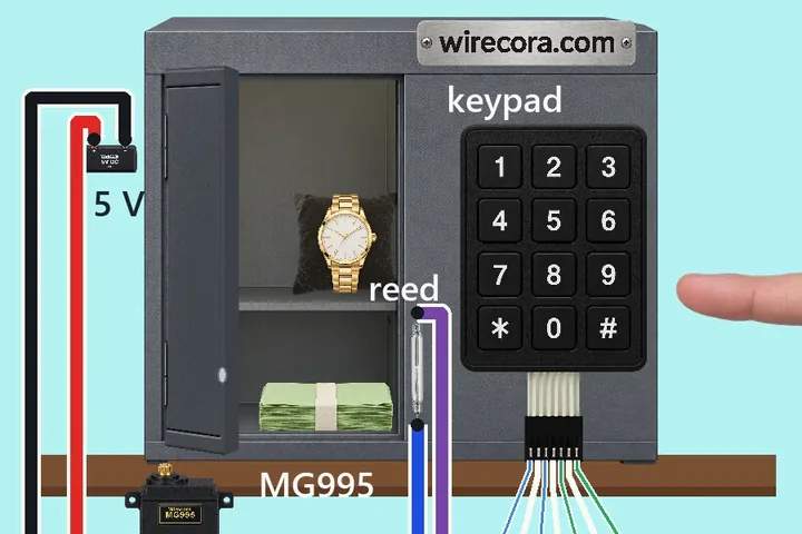 Same reed switch + buzzerKeypad code door with an Arduino, an MG995 servo and a reed switchType a wrong four-digit code and the screen says WRONG CODE, the buzzer buzzes and the backlight blinks.
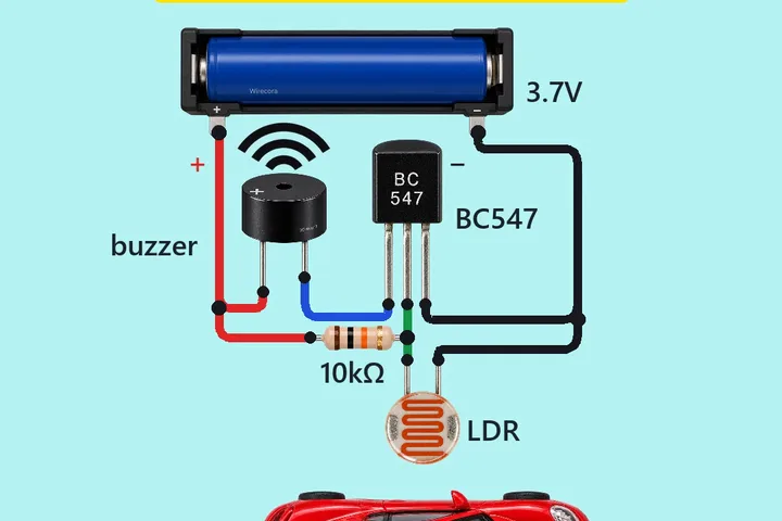 Next step: adds a light sensorLaser tripwire alarmA red laser shines on a light sensor and the buzzer stays quiet.
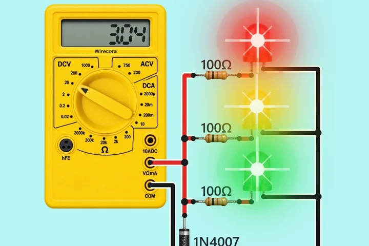 Something new: a motorHand-crank motor generatorA hand turns a crank on a small TT gear motor.