Servo that follows a knob: 10 k pot, Arduino Uno and an SG90
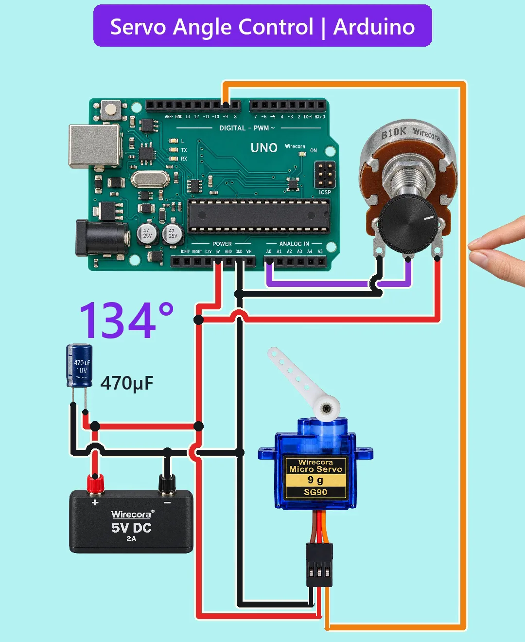
Turn the knob and the servo arm follows. A 10 k potentiometer gives the Arduino Uno a voltage on A0; the sketch turns that reading (0 to 1023) into an angle (0 to 180 degrees) and sends it to an SG90 servo on D9. In the Short the knob stops at readings of 259, 429, 594 and 764, which the sketch turns into 45, 75, 104 and 134 degrees.
- 6 parts
- 6 wiring steps
- Arduino code
- 5 V supply
Quick answer
The short version. Every pin is in the full wiring below.What you need
- Arduino Uno R3
- 10 k linear rotary potentiometer
- SG90 micro servo
- Regulated 5 V 2 A supply
- 470 uF 10 V electrolytic capacitor
- Jumper wires
How to wire it
- Pot left lug (terminal 1, counter-clockwise end) to GND.
- Pot middle lug (the wiper) to Uno A0.
- Servo orange lead (signal) to Uno D9.
- Supply + to the Uno 5V pin, and by its own wire to the servo red lead, the pot and the capacitor.
- 470 uF across the 5 V rail: the long leg on +5 V, the striped leg on GND.
- The 5V pin skips the Uno's own regulator, so feed it only a good regulated 5 V (never above about 5.5 V).
Before you power it: Everything runs on 5 V from a regulated supply. Use a regulated 5 V supply only on the 5V pin, nothing on VIN or the barrel jack at the same time, and no USB while the supply is connected. Keep fingers away from the moving horn.
Parts list
- Arduino Uno R3 (5 V)
- 10 k linear rotary potentiometer (B10K), with a knob
- SG90 micro servo (4.8 V, about 0.1 s per 60 degrees, brown = GND, red = +, orange = signal)
- Regulated 5 V 2 A supply
- 470 uF 10 V electrolytic capacitor (the stripe marks the minus lead)
- Jumper wires
Wiring, step by step
- Pot left lug (terminal 1, counter-clockwise end) to GND. Pot right lug (terminal 3, clockwise end) to +5 V. Seen with the shaft toward you and the lugs down, the lugs are 1 counter-clockwise, 2 wiper, 3 clockwise.
- Pot middle lug (the wiper) to Uno A0.
- Servo orange lead (signal) to Uno D9. Servo red lead to +5 V. Servo brown lead to GND.
- Supply + to the Uno 5V pin, and by its own wire to the servo red lead, the pot and the capacitor. Supply minus to the Uno GND pin and to the servo brown lead, the pot and the capacitor. All grounds are joined. VIN and the barrel jack stay empty.
- 470 uF across the 5 V rail: the long leg on +5 V, the striped leg on GND.
- The 5V pin skips the Uno's own regulator, so feed it only a good regulated 5 V (never above about 5.5 V). Do not plug in USB while the supply is connected: upload the sketch first, unplug USB, then connect the supply.
How it works
- The pot is a voltage divider: its ends sit on +5 V and GND, so the wiper gives 0 to 5 V on A0. Turning the knob clockwise raises the voltage, because the clockwise lug is on +5 V.
- analogRead(A0) turns that voltage into 0 to 1023. map(v, 0, 1023, 0, 180) turns it into an angle, and s.write(angle) sends it as a pulse of 544 us (0 degrees) to 2400 us (180 degrees), 50 times a second.
- In the Short: a reading of 259 (1.27 V) gives 45 degrees, 429 gives 75, 594 gives 104 and 764 (3.73 V) gives 134 degrees. A ngspice model of the drawn divider gives the same counts.
- The servo follows at no more than about 600 degrees per second (an SG90 does 60 degrees in 0.1 s), so an 89 degree swing takes about 0.15 s.
- Current from the 5 V supply: about 0.06 A idle, about 0.30 A while the servo moves and about 0.70 A if it stalls (typical SG90 figures), against 2 A. The pot draws 0.5 mA.
- The servo has its own wire from the supply and is not powered through the Uno. The 470 uF capacitor smooths the servo's current spikes; with a good supply it changes little, it helps more with long or thin wires or a weaker supply.
The code: servo_knob.ino
The Arduino code for this circuit is in the Wirecora Discord, in the channel #arduino-code (owner’s choice, 14 October 2026: the code lives where you can ask about it). It is a plain .ino file you can download there.
The sketch the Short was animated from. It uses the standard Servo library. Some servos turn the other way, and the angle per pulse varies between units.
What the video simplifies
- The servo is drawn from the side but its horn from above, turning in the picture plane.
- The big angle number is the value the sketch writes. The Uno has no display, and a real reading can wobble by about one degree.
- Clockwise on the knob gives a larger angle, which on a typical SG90 turns the horn counter-clockwise. Some servos turn the other way, and the angle per pulse varies by about 10 degrees between units.
- The hand turns the knob in three short twists per turn; the servo sound is synthesised.
- The original showed a second supply (a 4 x AA pack) for the servo, signal on pin 5 and a cross horn. This one uses a single 5 V supply, D9 and a single-arm horn.
- This circuit was checked by simulation and datasheets, not built.
You found this by searching. Here's the whole path.
- Read how it works
- See it work
- Try it on the board
- Build it
- Show it
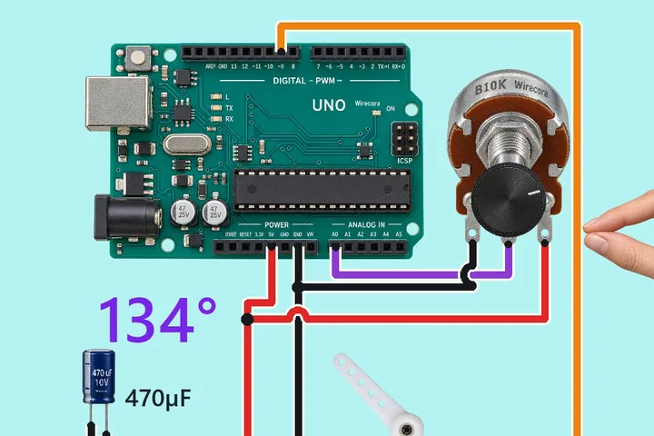
Thirty seconds of video shows the circuit doing its job. Then this whole circuit is on the wiring board. Wire it there first and watch it work before you touch a real part.
Everything runs on 5 V from a regulated supply. Use a regulated 5 V supply only on the 5V pin, nothing on VIN or the barrel jack at the same time, and no USB while the supply is connected. Keep fingers away from the moving horn.
Built it, or stuck halfway? Post a photo in the Wirecora Discord. Questions get an answer every day.
What to build next
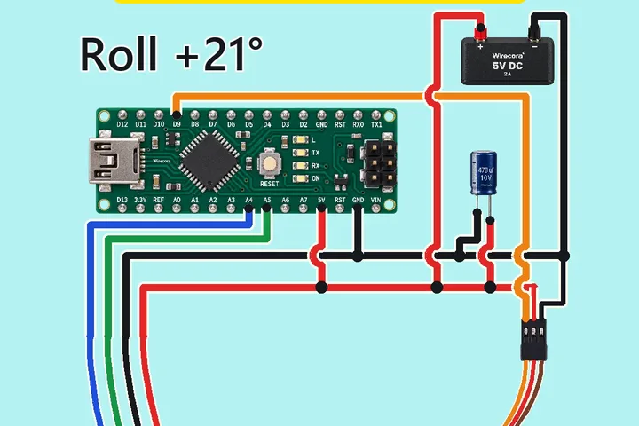 Same Arduino + servoOne-axis self-leveling gimbal: Arduino Nano, MPU6050 and an SG90A hand tilts the handle 25 degrees left and right.
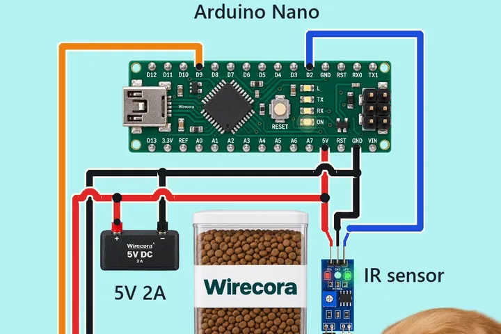 Next step: adds an IR sensorAutomatic pet feeder with an Arduino Nano, an IR sensor and a servo flapA dog, then a cat, walk up to the bowl.
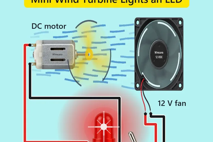 Something new: a motorMini wind turbine that lights an LED: a 12 V fan, a motor and a 100 ohm resistorA 12 V fan blows on a propeller fixed to a small DC motor.