Two servos fight over one switch
One switch, one LED and two servos that disagree. The orange arm keeps turning the light on, the blue arm keeps turning it off, and every push of the round comes faster than the last.
- 8 parts
- 7 wiring steps
- Arduino code
- 5 V supply
Quick answer
The short version. Every pin is in the full wiring below.What you need
- Arduino Nano
- SG90 micro servo, two of them
- MTS-102 mini toggle switch, SPDT
- 5 mm red LED
- 220 ohm resistor, in series with the LED
- 1000 uF 25 V electrolytic capacitor on the servo supply
- 5 V 2 A USB power adapter
- A small box with slots in the lid
How to wire it
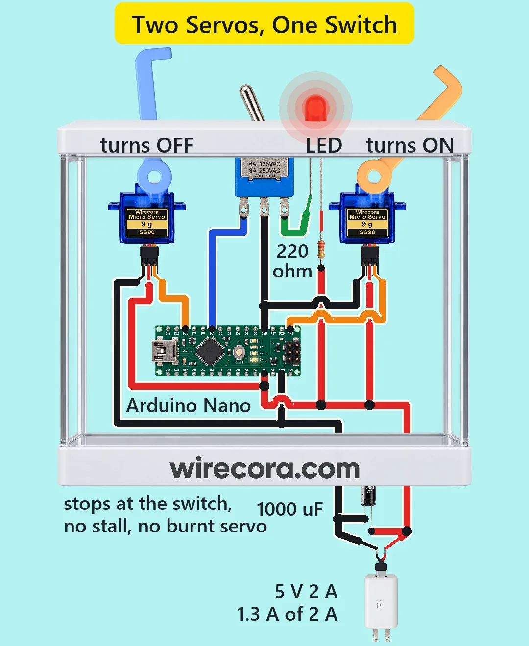
- Adapter plus to the Nano's 5V pin, both servo red leads, the 220 ohm resistor and the plus of the 1000 uF capacitor.
- Adapter minus to the Nano GND, the left servo's brown lead and the capacitor's stripe.
- The toggle's middle lug and the right servo's brown lead to the Nano's other GND pin.
- Toggle lug A to D7.
- Toggle lug B to the LED cathode.
- Left servo orange lead to D10.
- Right servo orange lead to D1 (the TX pin).
Before you power it: All 5 V. The servos never push at the same time and each stops when the switch flips; even with both stalled the draw would be about 1.3 A from a 2 A supply. The sketch's own safety choices: one supply with a common ground, a 1000 uF capacitor and arms that stop at the switch.
Parts list
- Arduino Nano
- SG90 micro servo, two of them (one turns the light off, one turns it on)
- MTS-102 mini toggle switch, SPDT
- 5 mm red LED
- 220 ohm resistor, in series with the LED (about 14 mA)
- 1000 uF 25 V electrolytic capacitor on the servo supply
- 5 V 2 A USB power adapter
- A small box with slots in the lid, two plastic arms and jumper wires
Wiring, step by step
- Adapter plus to the Nano's 5V pin, both servo red leads, the 220 ohm resistor and the plus of the 1000 uF capacitor. VIN needs 7 to 12 V, so it stays empty.
- Adapter minus to the Nano GND, the left servo's brown lead and the capacitor's stripe.
- The toggle's middle lug and the right servo's brown lead to the Nano's other GND pin.
- Toggle lug A to D7.
- Toggle lug B to the LED cathode. The LED anode goes through the 220 ohm resistor to 5 V.
- Left servo orange lead to D10.
- Right servo orange lead to D1 (the TX pin). Keep USB unplugged while the 5V pin is fed, and unplug this wire to upload the sketch.
How it works
- The toggle does two jobs. In one position it lights the LED straight through the 220 ohm resistor, with no code needed.
- In the other position it connects D7 to ground, and the LED is off.
- The Nano reads D7, knows whether the light is on and sends out the servo that hates that state: the left arm turns it off, the right arm turns it on.
- Each push gets faster: the sketch's step times shorten over eight pushes. An arm stops the moment the switch flips, so neither servo ever pushes against a stop.
The code: servo_fight.ino
The Arduino code for this circuit is in the Wirecora Discord, in the channel #arduino-code (owner’s choice, 14 October 2026: the code lives where you can ask about it). It is a plain .ino file you can download there.
From the Short's own checked drawing; it needs only the Servo library that comes with the Arduino software. It was checked by simulation, not run on a real box. The arm angles come from our drawing: tune L_HIT and R_HIT on your own box.
What the video simplifies
- The box front is clear and the arms are coloured so you can tell them apart. The LED stands in front of the arms' path.
- The speed-up over eight pushes is set in the sketch, and the slow first push is slowed on purpose.
- The servo currents, lever travel and the force a mini toggle needs are typical values, not measured. The LED is drawn larger and the adapter and capacitor smaller than life. The sounds are real recordings.
- This was checked by simulation and datasheets, not built.
You found this by searching. Here's the whole path.
- Read how it works
- See it work
- Build it
- Show it
Thirty seconds of video shows the circuit doing its job.
All 5 V. The servos never push at the same time and each stops when the switch flips; even with both stalled the draw would be about 1.3 A from a 2 A supply. The sketch's own safety choices: one supply with a common ground, a 1000 uF capacitor and arms that stop at the switch.
Built it, or stuck halfway? Post a photo in the Wirecora Discord. Questions get an answer every day.
What to build next
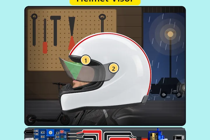 Same Arduino + servoHelmet that closes its own visorYou lower the helmet onto your head and the visor swings down by itself.
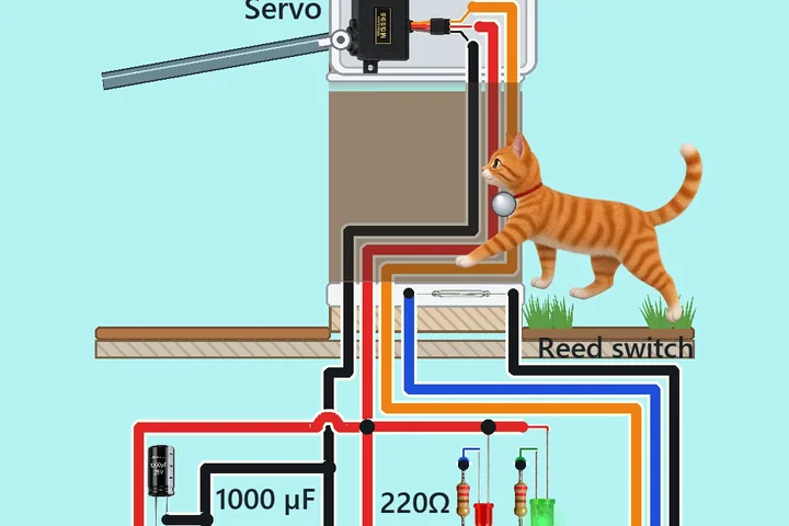 Next step: adds a reed switchSmart cat door with a magnet tagThe cat walks up to the door.
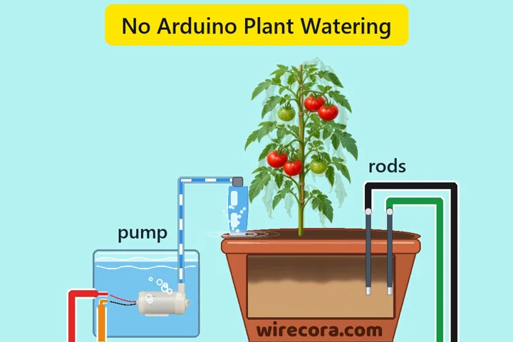 Something new: a pumpSelf-watering plant with one MOSFET (no Arduino)Two steel rods in the soil decide when the pump runs.