Automatic exhaust fan that turns on for smoke (Arduino Nano, MQ-2 and a relay)
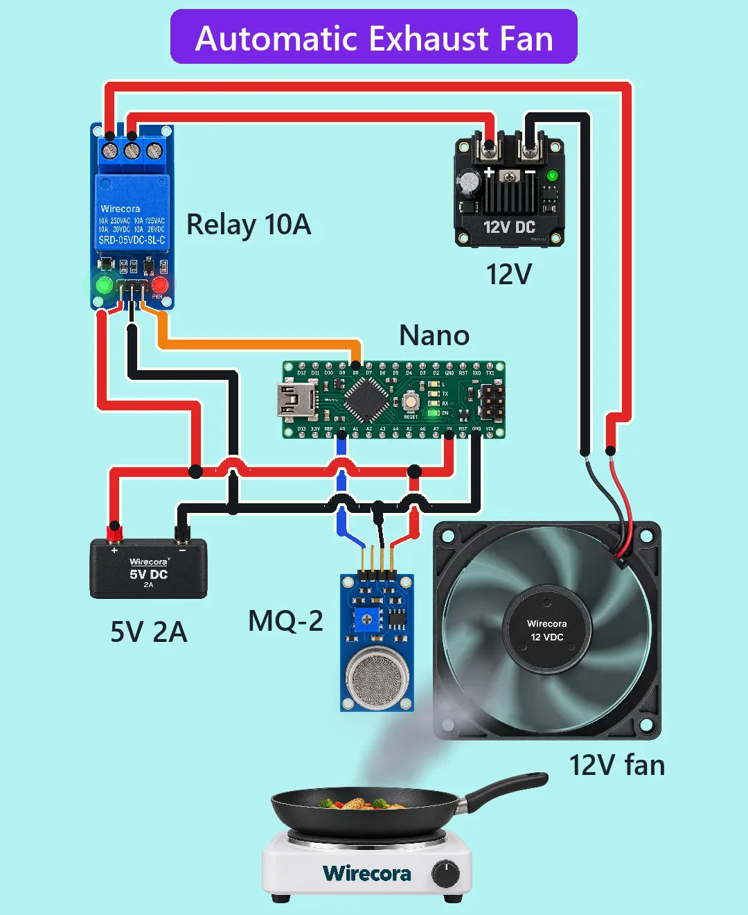
A frying pan starts to smoke. An MQ-2 gas and smoke sensor notices it, a relay clicks and a 12 V fan pulls the smoke away. When the air is clear again the fan stops.
- 6 parts
- 6 wiring steps
- Arduino code
- 12 V supply
Quick answer
The short version. Every pin is in the full wiring below.What you need
- Arduino Nano
- MQ-2 gas and smoke sensor module
- 1-channel 5 V relay module
- 12 V DC fan, 80 mm, about 75 mA
- 5 V 2 A supply for the Arduino side
- 12 V supply for the fan
How to wire it
- 5V to the Nano's 5V pin, the MQ-2's VCC and the relay module's VCC.
- MQ-2 AO to Nano A0.
- Nano D8 to relay IN.
- 12 V plus to the relay's COM.
- The 5 V side and the 12 V side share no wire.
- The picture shows the sensor side of the MQ-2 module.
Before you power it: Everything runs on 5 V and 12 V. Never switch a mains fan with this build. The MQ-2 is not a smoke alarm, so never rely on it to warn you of a fire; fit a certified smoke detector. Keep the sensor's hot heater away from anything that burns.
Parts list
- Arduino Nano
- MQ-2 gas and smoke sensor module (pins VCC, GND, DO, AO; the Short uses VCC, GND and AO; its heater draws about 160 mA)
- 1-channel 5 V relay module, low-level trigger, header VCC, GND, IN, terminals NO, COM, NC, contacts 10 A at 30 V DC
- 12 V DC fan, 80 mm, about 75 mA (red lead plus, black lead minus)
- 5 V 2 A supply for the Arduino side (about 0.26 A in use)
- 12 V supply for the fan
Wiring, step by step
- 5V to the Nano's 5V pin, the MQ-2's VCC and the relay module's VCC. GND to the Nano's GND, the MQ-2's GND and the relay module's GND.
- MQ-2 AO to Nano A0. DO is not connected.
- Nano D8 to relay IN.
- 12 V plus to the relay's COM. Relay NO to the fan's red lead. The fan's black lead to 12 V minus. NC is unused.
- The 5 V side and the 12 V side share no wire. Only the relay contacts join the fan to its supply.
- The picture shows the sensor side of the MQ-2 module. On a real board the pin names are on the back, so wire by name, not by position.
How it works
- The sketch reads A0. Above 400 it pulls D8 LOW, and a low-level-trigger relay module turns on at LOW. Below 300 the fan goes off. The gap between 300 and 400 stops chattering.
- The relay's COM to NO contact joins the fan to 12 V. The fan takes about 75 mA, a small part of the contacts' 10 A rating.
- The heater takes 5 V / 31 ohm = about 161 mA and the relay module about 75 mA, so the 5 V side uses about 0.26 A of its 2 A.
- The relay input draws about 2 to 4 mA from the Nano pin, well under the 20 mA limit.
- No diode is needed across a small brushless fan, because the fan has its own driver chip. The relay coil's flyback diode is on the module.
- On a high-level-trigger relay module, swap HIGH and LOW in the sketch.
The code: smoke_exhaust_fan.ino
The Arduino code for this circuit is in the Wirecora Discord, in the channel #arduino-code (owner’s choice, 14 October 2026: the code lives where you can ask about it). It is a plain .ino file you can download there.
The sketch the Short was animated from; it has not been run on a real board yet. The relay module is low-level trigger: LOW = fan on. For a high-level-trigger module swap HIGH and LOW. Pin 8 is set HIGH before pinMode so the relay does not click at power-up.
What the video simplifies
- The smoke, the reading and the 6 second cycle are a model. A real MQ-2 needs minutes of warm-up, and over 48 hours when new. It reads high while cold and reacts over seconds. The value 400 is a demo threshold.
- It also reacts to LPG, alcohol and hydrogen, and it is no certified smoke alarm.
- The fan speeds up and stops faster than a real one, the blades are drawn slower than real, and the parts are larger than the pan.
- A real sensor sits higher, beside the hood and away from heat, steam and grease. A real exhaust fan is mounted in a wall.
- Fixed from the viral original: a safe 12 V fan on its own supply in place of the 230 V mains fan.
- This circuit was checked by simulation and datasheets, not built.
You found this by searching. Here's the whole path.
- Read how it works
- See it work
- Build it
- Show it
Thirty seconds of video shows the circuit doing its job.
Everything runs on 5 V and 12 V. Never switch a mains fan with this build. The MQ-2 is not a smoke alarm, so never rely on it to warn you of a fire; fit a certified smoke detector. Keep the sensor's hot heater away from anything that burns.
Built it, or stuck halfway? Post a photo in the Wirecora Discord. Questions get an answer every day.
What to build next
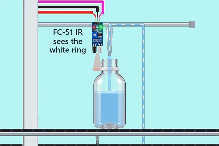 Same Arduino + relayArduino bottle filler with one relayA belt brings an empty bottle.
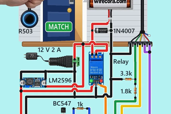 Next step: adds a buzzerFingerprint door lock with an Arduino and an R503Touch the sensor's ring with an enrolled finger: about half a second later the ring turns blue, the relay clicks and the solenoid pulls its bolt back, so the little door swings open with a push.
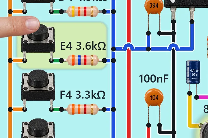 Something new: a 555 timerSix-key electronic piano with one NE555 timerPress a key and the speaker sings a note.