Automatic solar night light with a TP4056, a BC557 and an 18650 cell
A 6 V solar panel charges an 18650 cell through a TP4056 module all day. At sunset three white LEDs switch on by themselves, and at sunrise they switch off. The panel is also the light sensor.
- 7 parts
- 6 wiring steps
- No code needed
Quick answer
The short version. Every pin is in the full wiring below.What you need
- 6 V 1 W solar panel
- 1N5819 Schottky diode
- TP4056 charger module with protection
- Protected 18650 Li-ion cell in a holder
- BC557B PNP transistor
- 100 ohm resistor and 1k resistor
- Three 5 mm white LEDs and three 68 ohm resistors
How to wire it
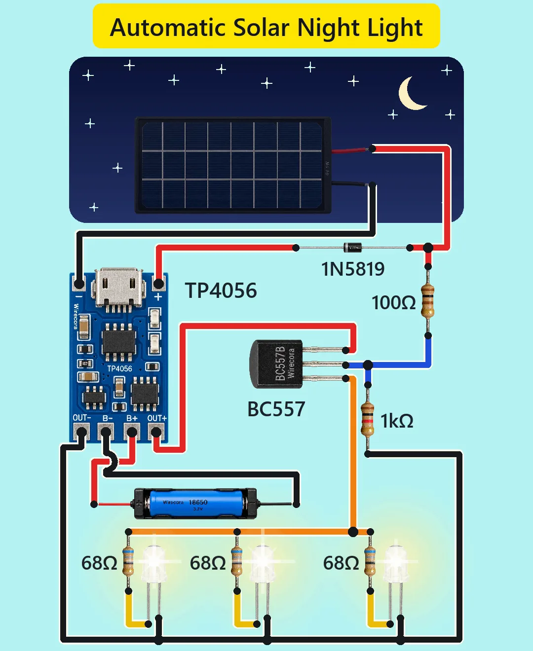
- Panel plus through the 1N5819 (band toward the module) to the TP4056's IN+.
- Cell plus to B+, cell minus to B-.
- OUT+ to the BC557's emitter.
- 100 ohm from panel plus (at the diode's anode) to the BC557's base.
- BC557 collector to the three 68 ohm resistors, each then to its own white LED's anode.
- In the drawing the cell's B- wire hops over the B+ wire once.
Before you power it: Use a protected 18650 cell and a TP4056 board with protection, and never short the cell: lithium cells can catch fire. Use only a 6 V panel; a bigger one can push the TP4056 over its 8 V limit. Never charge the cell unattended in a closed box.
Parts list
- 6 V 1 W solar panel (open circuit about 7.2 V, short circuit about 180 mA; use only a 6 V panel)
- 1N5819 Schottky diode (40 V, 1 A; the band is the cathode)
- TP4056 charger module with protection (03962A board: TP4056 + DW01A + FS8205A), pads IN-, IN+ at the top and OUT-, B-, B+, OUT+ at the bottom
- Protected 18650 Li-ion cell in a holder (3.7 V nominal; the Short assumes 2000 mAh)
- BC557B PNP transistor (legs from the left, flat face toward you: collector, base, emitter)
- 100 ohm resistor and 1k resistor
- Three 5 mm white LEDs and three 68 ohm resistors
Wiring, step by step
- Panel plus through the 1N5819 (band toward the module) to the TP4056's IN+. Panel minus to IN-.
- Cell plus to B+, cell minus to B-. The lights run from the protected OUT+ and OUT-, so the module's protection covers the LEDs. On this board OUT+ is B+ and OUT- is the protected negative, the same as IN-.
- OUT+ to the BC557's emitter.
- 100 ohm from panel plus (at the diode's anode) to the BC557's base. 1k from the base to ground (OUT-).
- BC557 collector to the three 68 ohm resistors, each then to its own white LED's anode. All three LED cathodes to ground.
- In the drawing the cell's B- wire hops over the B+ wire once. Where a wire hops over another, they do not touch.
How it works
- In daylight the panel holds the PNP's base high through the 100 ohm resistor, so the transistor is off and the LEDs are dark, while the TP4056 charges the cell: about 173 mA in full sun, with the red CHRG LED on.
- In the dark the panel gives no current, the 1k resistor pulls the base toward ground and the PNP turns on: about 2.9 mA of base current at 3.7 V. The three LEDs get about 9 mA each, about 30 mA from the cell.
- The switch point is about 2 % of full sun (1 to 5 % depending on cell voltage, panel and temperature).
- A full 2000 mAh cell runs the lights about 50 hours before the LED current halves. One 12 hour night uses about 366 mAh. At 4.2 V the LEDs get 15 to 17 mA each and they dim near 3.0 V.
- The TP4056 runs in dropout while charging: its input sits at about 3.8 V, below its 4.0 V rated minimum. In weak light, or with the cell below about 3.5 V, it charges in bursts. With a full cell the input rises to about 7 V, and to the chip's 8 V maximum with a freezing panel (some clones are rated lower). That is why only a 6 V panel is used.
- A full charge in full sun takes about 12 to 13 hours. One sunny day with about 5 full-sun hours returns about 0.87 Ah, more than a night uses.
What the video simplifies
- The 5 second day stands for about a whole day.
- Sun, sky, moon, stars, the sheen on the panel, the glows and the sparkle are drawn, and the sound is illustrative. The sun sets and rises on the same side of the sky, which a real sun does not.
- Real lights switch on in twilight and fade over minutes. Here the LEDs switch within about one frame, and the red LED fades smoothly instead of flickering.
- The 2000 mAh capacity and a protected cell are assumed; the cell's art prints only 18650 3.7V.
- Which of the module's two SMD LEDs is the CHRG LED is an assumption: the lower one. The upper STDBY LED stays unlit.
- Inspired by a viral solar power bank (TP4056 + MT3608), rebuilt as the classic automatic night light.
- This circuit was checked by an ngspice simulation and datasheets, not built.
You found this by searching. Here's the whole path.
- Read how it works
- See it work
- Build it
- Show it
Thirty seconds of video shows the circuit doing its job.
Use a protected 18650 cell and a TP4056 board with protection, and never short the cell: lithium cells can catch fire. Use only a 6 V panel; a bigger one can push the TP4056 over its 8 V limit. Never charge the cell unattended in a closed box.
Built it, or stuck halfway? Post a photo in the Wirecora Discord. Questions get an answer every day.
What to build next
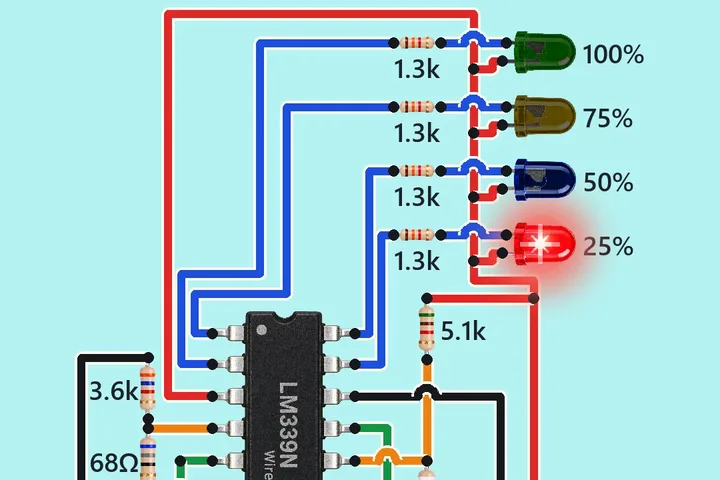 Similar parts12 V battery level indicator with four LEDsThe battery's voltage falls and the four LEDs go out from the top: green (100 %) first, then yellow, blue and red (25 %).
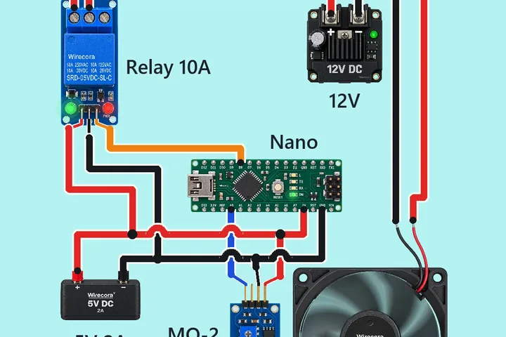 Something new: an ArduinoAutomatic exhaust fan that turns on for smoke (Arduino Nano, MQ-2 and a relay)A frying pan starts to smoke.
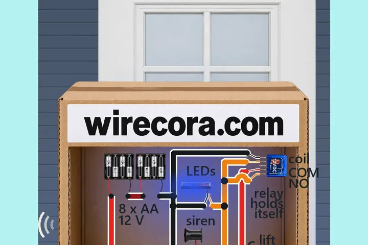 Similar partsParcel alarm that keeps goingLift the parcel and a siren sounds with red and blue strobe flashes.